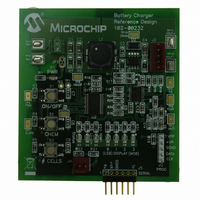
MCP1631RD-MCC2 Microchip Technology, MCP1631RD-MCC2 Datasheet - Page 40

MCP1631RD-MCC2
Manufacturer Part Number
MCP1631RD-MCC2
Description
REFERENCE DESIGN MCP1631HV
Manufacturer
Microchip Technology
Datasheets
1.MCP1631VHVT-330EST.pdf
(34 pages)
2.MCP1631HV-330EST.pdf
(54 pages)
3.MCP1631RD-MCC2.pdf
(20 pages)
4.MCP1631RD-MCC2.pdf
(328 pages)
Specifications of MCP1631RD-MCC2
Main Purpose
Power Management, Battery Charger
Embedded
Yes, MCU, 8-Bit
Utilized Ic / Part
MCP1631HV, PIC16F883
Primary Attributes
1 ~ 2 Cell- Li-Ion, 1 ~ 5 Cell- NiCd/NiMH, 1 ~ 2 1W LEDs
Secondary Attributes
Status LEDs
Silicon Manufacturer
Microchip
Application Sub Type
Battery Charger
Kit Application Type
Power Management - Battery
Silicon Core Number
MCP1631HV, PIC16F883
Kit Contents
Board
Lead Free Status / RoHS Status
Lead free / RoHS Compliant
Lead Free Status / RoHS Status
Lead free / RoHS Compliant
MCP1631HV Multi-Chemistry Battery Charger Reference Design
DS51791A-page 36
30. EE_CHEMISTRY_DEFAULT = LiIon
31. EE_NUMBER_OF_CELLS_DEFAULT = 2
32. EE_LION_CAL_VOLTAGE_DEFAULT = ((int)((float)(4200.00 /
33. EE_CHARGE_TIMEOUT_DEFAULT = (5*60*60)
34. OSCILLATOR_DUTY_CYCLE = 25
35. RS232_DATALOGGING = ENABLED
36. THERMISTOR_SUPPORT = ENABLED
37. LED_DRIVER_SUPPORT = ENABLED
38. LED_DRIVER_OVER_VOLTAGE = ((int)(3600.0 / BATTERY_MV_PER_BIT))
39. LED_DRIVER_CONDITION_CURRENT =
40. LED_DRIVER_CONDITION_VOLTAGE = ((int)(0.0/ BATTERY_MV_PER_BIT))
41. LED_DRIVER_CURRENT = ((int)(300.0 / BATTERY_MA_PER_BIT))
42. LED_DRIVER_OVTEMP_SETPOINT = ((float)(THERMISTOR_OHMS_45C))
43. MAX_LED_CELLS = 2
Maximum charging time.
NiMH = Use (C rating in mAh/Charge Current) + 1hr Topoff + 0.25hr pre-condition)
*60 sec * 60 min
Lithium Ion = Use about 2.5 * (C rating in mAh/Charge Current) * 60 sec * 60 min
Default Chemistry.
Default number of cells value.
BATTERY_MV_PER_BIT)))
Default Lithium Ion battery calibration value.
Oscillator duty cycle in percent. Must be in 1/16th intervals due to 4 bit counter.
Set to ENABLE for logging data out to USART port and PICkit
Set to DISABLED to remove logging code.
Set to ENABLE for thermistor support. Used for NiMH and NiCD charging.
Set to DISABLED to remove thermistor code.
Set to ENABLE for LED driver support.
Set to DISABLED to remove LED driver code.
Set this value to the voltage in mV that is the absolute limit of each single LED.
The system will go into overvoltage shutdown mode if the output voltage exceeds
this value times the number of LED series connected cells being driven.
((int)(10.0/BATTERY_MA_PER_BIT))
LED conditioning (startup) current.
LED conditioning voltage is 0 volts. No conditioning required.
LED Driver current maximum value. This is the upper current limit value that the
driver will deliver to the LED output.
Optional LED overtemperature limit may be used to limit LED temperature.
Set LED_DRIVER_OVTEMP_SETPOINT to one of the Thermistor Ohms
definitions for the desired shutdown temperature.
Maximum number of 1W LED cells in series that will be driven by the driver
output.
© 2009 Microchip Technology Inc.
TM
Serial Analyzer.


