MCP23X17EV Microchip Technology, MCP23X17EV Datasheet - Page 13
MCP23X17EV
Manufacturer Part Number
MCP23X17EV
Description
BOARD EVAL FOR MCP23X17
Manufacturer
Microchip Technology
Specifications of MCP23X17EV
Main Purpose
Interface, GPIO Expander
Embedded
Yes, MCU, 8-Bit
Utilized Ic / Part
MCP23017, MCP23S17
Primary Attributes
(2) 16-Bit GPIO Expanders, I2C and SPI
Secondary Attributes
4 Momentary Switches, 12 LEDs
Processor To Be Evaluated
MCP23x17
Data Bus Width
16 bit
Interface Type
SPI
Silicon Manufacturer
Microchip
Silicon Core Number
MCP23017, MCP23S17
Kit Application Type
Interface
Application Sub Type
GPIO Expander
Kit Contents
Board
Rohs Compliant
Yes
Lead Free Status / RoHS Status
Lead free / RoHS Compliant
Lead Free Status / RoHS Status
Lead free / RoHS Compliant, Lead free / RoHS Compliant
Available stocks
Company
Part Number
Manufacturer
Quantity
Price
Company:

Part Number:
MCP23X17EV
Manufacturer:
MICROCHIP
Quantity:
12 000


2.4
2.5
© 2006 Microchip Technology Inc.
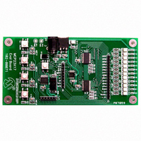
MCP23X17 EVALUATION BOARD DESCRIPTION
FIRMWARE DESCRIPTION
2.4.1
1. MCP23017 and MCP23S17 - The two devices under evaluation/demonstration.
2. LEDs - These are connected to the MCP23X17 GPIO configured as outputs.
3. Momentary Buttons - These are connected to the MCP23X17 configured as
4. PIC16F818 - Reads the selector switch and controls the MCP23X17 devices.
5. Headers - There are two headers which are connected to the MCP23X17 pins to
6. Jumpers - The jumpers are used to isolate the MCP23X17 pins so they can be
7. Power - The boards can be powered by 9V via the power jack (J2) or by applying
See Figure 2-2 for the main firmware flow diagram
1. The firmware first configures the PIC16F818 microcontroller.
2. The firmware configures the MCP23X17 devices (4-inputs, 12-outputs, enable
3. The firmware checks the selector switch to determine which MCP23X17 to
4. The “other” MCP23X17 is configured to all inputs so that it does not cause
5. The MCP23X17 inputs are sampled.
6. The LEDs light up in a pattern as defined by the button which was pressed. If no
Both devices are connected to the same inputs and outputs and selector switch
is used to select which device the PICmicro controls. A mux is used to route the
serial (I
inputs.
allow off-board connections.
connected to an off-board circuit. The jumpers are not populated, however, they
are shorted by a trace on the bottom of the PCB.
5V directly to the power points (TP1 and TP2).
interrupts, etc.).
communicate with during the main loop.
contention on LED connections.
button is pressed, the LEDs maintain the current sequence.
Major Board Components
2
C or SPI) from the PICmicro to the MCP23X17.
DS51592B-page 9
Related parts for MCP23X17EV
Image
Part Number
Description
Manufacturer
Datasheet
Request
R

Part Number:
Description:
MCP2,8 RECEPTACLE CONTACT
Manufacturer:
TE Connectivity
Datasheet:

Part Number:
Description:
MCP2,8 BU-KONT EDS
Manufacturer:
TE Connectivity
Datasheet:

Part Number:
Description:
MCP2,8 BU-CONTACT EDS
Manufacturer:
Tyco Electronics
Datasheet:
Part Number:
Description:
MCP2,8 SOCKET CONT SWS
Manufacturer:
Tyco Electronics
Datasheet:
Part Number:
Description:
MCP2,8 BU-CONTACT EDS
Manufacturer:
Tyco Electronics
Datasheet:
Part Number:
Description:
MCP2,8 BU-CONTACT EDS
Manufacturer:
Tyco Electronics
Datasheet:
Part Number:
Description:
MCP2,8 BU-CONTACT EDS
Manufacturer:
Tyco Electronics
Datasheet:
Part Number:
Description:
MCP2,8 BU-CONTACT EDS
Manufacturer:
Tyco Electronics
Datasheet:
Part Number:
Description:
MCP2,8 BU-CONTACT EDS
Manufacturer:
Tyco Electronics
Datasheet:
Part Number:
Description:
MCP2,8 BU-CONTACT EDS
Manufacturer:
Tyco Electronics
Datasheet:

Part Number:
Description:
Manufacturer:
Microchip Technology Inc.
Datasheet:
Part Number:
Description:
Manufacturer:
Microchip Technology Inc.
Datasheet:
Part Number:
Description:
Manufacturer:
Microchip Technology Inc.
Datasheet: