MCP23X17EV Microchip Technology, MCP23X17EV Datasheet
MCP23X17EV
Specifications of MCP23X17EV
Available stocks


Related parts for MCP23X17EV


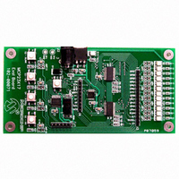
MCP23X17EV Summary of contents
Page 1
... Mapping Interrupts - Mirroring Interrupts (MCP23X17 only) - Servicing Interrupts • Internal Address Pointer Control • Hardware Address Pin on SPI © 2006 Microchip Technology Inc. AN1043 I/O PORT DESCRIPTION The I/O port is highly configurable for maximum flexibility. Figure simplified block diagram of an I/O port pin. The port can either drive logic levels on the pin, or read logic levels from the pad ...
Page 2
... GPINTENA 04 05 GPINTENB 05 06 DEFVALA 06 07 DEFVALB 07 08 INTCONA 08 09 INTCONB 09 0A IOCON 0A 10 IOCON 0B 11 GPPUA 0C 12 GPPUB 0D 13 INTFA 0E 14 INTFB 0F 15 INTCAPA 10 16 INTCAPB 11 17 GPIOA 12 18 GPIOB 13 19 OLATA 14 1A OLATB 15 © 2006 Microchip Technology Inc. ...
Page 3
... FIGURE 2: INTERRUPT BLOCK DIAGRAM IOCON.ODR IOCON.INTPOL IOCON.MIRROR A B © 2006 Microchip Technology Inc. Interrupt Conditions There are several configurable interrupt conditions which allow flexible configurations. INTERRUPT-ON-PIN-CHANGE Pins configured for interrupt-on-pin-change will cause an interrupt to occur if a pin changes to the opposite state. The default state is reset after an interrupt is serviced ...
Page 4
... X X IOC4 IOC3 IOC2 IOC1 DEF4 DEF3 DEF2 DEF1 Interrupt will occur if GP3 logic level = 1 INT remains because GP3 = 1 (opposite of DEF3) Read INTCAP or GPIO Read INTCAP or GPIO X IOC0 X DEF0 X GP3 = DEF3 INT deactivates after SPI read © 2006 Microchip Technology Inc. ...
Page 5
... INTCAPB 18 GPIOB 19 OLATB 1A © 2006 Microchip Technology Inc. For example, when configuring the device, it may be desirable to allow the address pointer to automatically increment so the device does not have to be re- addressed after every byte. Likewise, when performing a continuous operation on a register (e.g., changing the outputs on a regular basis ...
Page 6
... Also, the initial address can be either register address (e.g., 14h or 15h) and the pointer will still alternate between the registers Data @ 12h ENABLED and the device Data @ Data @ 0Ah 10h DISABLED and the device Data @ Data @ 13h 12h © 2006 Microchip Technology Inc. ...
Page 7
... INTFB 0F INTCAPA 10 INTCAPB 11 GPIOA 12 GPIOB 13 OLATA 14 OLATB 15 © 2006 Microchip Technology Inc. When the address pointer is 16-bit mode, the address pointer will increment after every byte is clocked. The address pointer will roll over to 00h after exceeding 15h Data @ Data @ 12h AN1043 ...
Page 8
... MCU pin for chip select (see Figure 9). MCP23S17 CS GP15 SCK . SPI SDI . SDO . GPIO . Port . A2 . Addr A1 . Pins A0 GP0 MCP23X17 Register Addr Opcode MCP23S08 GP7 . . . GP0 © 2006 Microchip Technology Inc. ...
Page 9
... PowerMate, PowerTool, REAL ICE, rfLAB, rfPICDEM, Select Mode, Smart Serial, SmartTel, Total Endurance, UNI/O, WiperLock and ZENA are trademarks of Microchip Technology Incorporated in the U.S.A. and other countries. SQTP is a service mark of Microchip Technology Incorporated in the U.S.A. All other trademarks mentioned herein are property of their respective companies. ...
Page 10
... Fax: 886-3-572-6459 Taiwan - Kaohsiung Tel: 886-7-536-4818 Fax: 886-7-536-4803 Taiwan - Taipei Tel: 886-2-2500-6610 Fax: 886-2-2508-0102 Thailand - Bangkok Tel: 66-2-694-1351 Fax: 66-2-694-1350 © 2006 Microchip Technology Inc. EUROPE Austria - Wels Tel: 43-7242-2244-3910 Fax: 43-7242-2244-393 Denmark - Copenhagen Tel: 45-4450-2828 Fax: 45-4485-2829 France - Paris Tel: 33-1-69-53-63-20 ...