MCP23X17EV Microchip Technology, MCP23X17EV Datasheet - Page 3
MCP23X17EV
Manufacturer Part Number
MCP23X17EV
Description
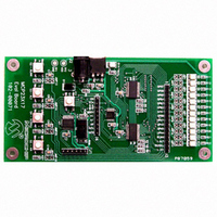
BOARD EVAL FOR MCP23X17
Manufacturer
Microchip Technology
Specifications of MCP23X17EV
Main Purpose
Interface, GPIO Expander
Embedded
Yes, MCU, 8-Bit
Utilized Ic / Part
MCP23017, MCP23S17
Primary Attributes
(2) 16-Bit GPIO Expanders, I2C and SPI
Secondary Attributes
4 Momentary Switches, 12 LEDs
Processor To Be Evaluated
MCP23x17
Data Bus Width
16 bit
Interface Type
SPI
Silicon Manufacturer
Microchip
Silicon Core Number
MCP23017, MCP23S17
Kit Application Type
Interface
Application Sub Type
GPIO Expander
Kit Contents
Board
Rohs Compliant
Yes
Lead Free Status / RoHS Status
Lead free / RoHS Compliant
Lead Free Status / RoHS Status
Lead free / RoHS Compliant, Lead free / RoHS Compliant
Available stocks
Company
Part Number
Manufacturer
Quantity
Price
Company:

Part Number:
MCP23X17EV
Manufacturer:
MICROCHIP
Quantity:
12 000


INTERRUPT FEATURES
The MCP23X08 has one interrupt pin and the
MCP23X17 has two interrupt pins.
For the MCP23X17, each interrupt pin is associated
with an 8-bit port. INTA is associated with Port A and
INTB is associated with Port B.
Interrupt Mapping
The MCP23X17 interrupt pins can be mapped in two
ways (see Figure 2) as controlled by IOCON.MIRROR:
1.
2.
Interrupt Polarity and Open-Drain
The interrupts can be configured to operate in three
modes:
1.
2.
3.
The interrupt polarity and open-drain is configured via
INTPOL and ODR bits in the IOCON register.
FIGURE 2:
© 2006 Microchip Technology Inc.
Note:
Interrupt pins operate independently. INTA
reflects interrupt conditions on Port A and INTB
reflects interrupt conditions on Port B.
Both interrupt pins go active when an interrupt
occurs on either port.
Active-High.
Active-Low.
Open-Drain.
For the MCP23X17, the polarity and open-
drain configuration of the INTA and INTB
pins are not independent. Both pins are
configured the same.
IOCON.MIRROR
A
B
IOCON.INTPOL
INTERRUPT BLOCK DIAGRAM
IOCON.ODR
0
1
0
1
Interrupt Conditions
There are several configurable interrupt conditions
which allow flexible configurations.
INTERRUPT-ON-PIN-CHANGE
Pins configured for interrupt-on-pin-change will
cause an interrupt to occur if a pin changes to the
opposite state. The default state is reset after an
interrupt is serviced. For example, an interrupt occurs
by an input changing from 1 to 0. The interrupt is then
serviced while the pin state is still 0 by reading GPIO or
INTCAP register. The new initial state for the pin is a
logic 0. Likewise, if the pin is toggled back to a logic 1
before servicing the interrupt, the new default state is a
logic 1.
The interrupt condition is cleared by reading either
INTCAP or GPIO register. The new pin state default is
set when the interrupt is cleared.
INTERRUPT-ON-CHANGE FROM DEFVAL
REGISTER VALUE
Pins
register value will cause an interrupt to occur if the
corresponding input pin differs from the register bit. The
interrupt condition will remain as long as the condition
exists, regardless if the INTCAP or GPIO is read.
For example, if DEFVAL<b0> = 0. An interrupt will
occur if the pin changes to a logic 1 and the interrupt
will remain as long as the pin remains a logic 1. The
interrupt condition will clear if the pin changes back to
a logic 0 and INTCAP or GPIO is read.
Polarity
Control
configured
Control
Open-
Drain
for
interrupt-on-change
INTA
INTB
AN1043
DS01043A-page 3
from
Related parts for MCP23X17EV
Image
Part Number
Description
Manufacturer
Datasheet
Request
R

Part Number:
Description:
MCP2,8 RECEPTACLE CONTACT
Manufacturer:
TE Connectivity
Datasheet:

Part Number:
Description:
MCP2,8 BU-KONT EDS
Manufacturer:
TE Connectivity
Datasheet:

Part Number:
Description:
MCP2,8 BU-CONTACT EDS
Manufacturer:
Tyco Electronics
Datasheet:
Part Number:
Description:
MCP2,8 SOCKET CONT SWS
Manufacturer:
Tyco Electronics
Datasheet:
Part Number:
Description:
MCP2,8 BU-CONTACT EDS
Manufacturer:
Tyco Electronics
Datasheet:
Part Number:
Description:
MCP2,8 BU-CONTACT EDS
Manufacturer:
Tyco Electronics
Datasheet:
Part Number:
Description:
MCP2,8 BU-CONTACT EDS
Manufacturer:
Tyco Electronics
Datasheet:
Part Number:
Description:
MCP2,8 BU-CONTACT EDS
Manufacturer:
Tyco Electronics
Datasheet:
Part Number:
Description:
MCP2,8 BU-CONTACT EDS
Manufacturer:
Tyco Electronics
Datasheet:
Part Number:
Description:
MCP2,8 BU-CONTACT EDS
Manufacturer:
Tyco Electronics
Datasheet:

Part Number:
Description:
Manufacturer:
Microchip Technology Inc.
Datasheet:
Part Number:
Description:
Manufacturer:
Microchip Technology Inc.
Datasheet:
Part Number:
Description:
Manufacturer:
Microchip Technology Inc.
Datasheet: