AC164120 Microchip Technology, AC164120 Datasheet - Page 12
AC164120
Manufacturer Part Number
AC164120
Description
BOARD SIGNAL ANALYSIS PICKIT
Manufacturer
Microchip Technology
Series
PICtail™r
Specifications of AC164120
Main Purpose
Interface, Signal Analysis
Embedded
Yes, MCU, 8-Bit
Utilized Ic / Part
PICkit™ PICtail™1
Primary Attributes
Real-time Strip Chart, Oscilloscope, Fast Fourier Transformation (FFT)
Secondary Attributes
Histogram
Silicon Manufacturer
Microchip
Core Architecture
PIC
Core Sub-architecture
PIC16
Features
Real-Time Strip Chart, Fast Fourier Transformation
Silicon Core Number
PIC16F
Silicon Family Name
PIC16F6xxx
Rohs Compliant
Yes
Lead Free Status / RoHS Status
Lead free / RoHS Compliant
For Use With
PICkit Flash Starter Kit
Lead Free Status / RoHS Status
Lead free / RoHS Compliant, Lead free / RoHS Compliant
Available stocks
Company
Part Number
Manufacturer
Quantity
Price
Company:

Part Number:
AC164120
Manufacturer:
Microchip Technology
Quantity:
135


Signal Analysis PICtail™ Daughter Board User’s Guide
DS51476A-page 8
1.4.1
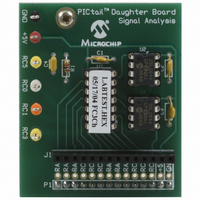
Figure 1-1 shows the PCB layout of the Signal Analysis board. It is populated with a
PIC16F684 and two 25LC640 serial EEPROM memory devices. The PIC16F684 I/O
pins RC0, RC1 and RC3 are connected directly to test point connections on the edge
of the PCB. These can be configured as comparator analog inputs (RC0/AN4,
RC1/AN5), analog-to-digital converter inputs (RC0/AN4, RC1/AN5, RC3/AN7) or as
digital input/output pins. I/O pin RC5 is connected through a RC filter (R1 and C4) to a
test point connection. RC5 is the P1A output of the Enhanced Capture/Compare/Pulse
Width Modulation (ECCP) module. It can be configured for digital PWM output.
Additionally, +5V and ground test points are available as test point connections.
Two 25LC640 SPI™ compatible serial EEPROM memory devices provide 8-bit by 16K
bytes of non-volatile memory. They are used in conjunction with the signal analysis
firmware (PICA2Dlab.hex) program to store data at a specified sample rate. For non
real-time acquisition modes (oscilloscope, FFT and histogram), the PC program
downloads the data from the 25LC640’s for computation and display.
Connector J1 allows additional circuit boards (for example temperature, light or
pressure sensors) to be plugged into the Signal Analysis board for signal measurement
and analysis. All port pins from the PIC16F684 are available on the J1 connector.
FIGURE 1-1:
PCB Layout and Parts
J1
P1
SIGNAL ANALYSIS PICtail™ DAUGHTER BOARD
PICtail™ Daughter Board
C1
U1
Signal Analysis
2004 Microchip Technology Inc.
U2
U3
Related parts for AC164120
Image
Part Number
Description
Manufacturer
Datasheet
Request
R

Part Number:
Description:
Manufacturer:
Microchip Technology Inc.
Datasheet:
Part Number:
Description:
Manufacturer:
Microchip Technology Inc.
Datasheet:
Part Number:
Description:
Manufacturer:
Microchip Technology Inc.
Datasheet:
Part Number:
Description:
Manufacturer:
Microchip Technology Inc.
Datasheet:
Part Number:
Description:
Manufacturer:
Microchip Technology Inc.
Datasheet:
Part Number:
Description:
Manufacturer:
Microchip Technology Inc.
Datasheet:
Part Number:
Description:
Manufacturer:
Microchip Technology Inc.
Datasheet:
Part Number:
Description:
Manufacturer:
Microchip Technology Inc.
Datasheet: