UM245R FTDI, Future Technology Devices International Ltd, UM245R Datasheet - Page 20
UM245R
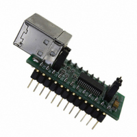
Manufacturer Part Number
UM245R
Description
MODULE USB-PAR FIFO TTL 24-DIP
Manufacturer
FTDI, Future Technology Devices International Ltd
Datasheet
1.UM245R.pdf
(27 pages)
Specifications of UM245R
Main Purpose
Interface, USB 2.0 to Parallel FIFO Bridge
Embedded
No
Utilized Ic / Part
FT245R
Primary Attributes
300kBps to 1MBps USB to parallel FIFO via 4-Wire Interface
Secondary Attributes
Royalty-Free Drivers
Lead Free Status / RoHS Status
Lead free / RoHS Compliant
Other names
768-1020


7.2 Self Powered Configuration
Figure 7.2 Self-Powered Configuration
Figure 7.2 illustrates the UM245R in a typical USB self powered configuration. In this case the link on
jumper J2 is removed, and an external supply is connected to the module VCC pins. Figure 7.2 illustrate
a design which has a 4.0V - 5V supply.
A USB Self Powered device gets its power from its own power supply and does not draw current from the
USB bus. The basic rules for USB Self power devices are as follows:
The power descriptor in the internal EEPROM should be programmed to a value of zero (self powered).
In order to meet requirement (i) the USB Bus Power is used to control the RESET# Pin of the FT245R
device. When the USB Host or Hub is powered up the internal 1.5kΩ resistor on USBDP is pulled up to
3.3V, thus identifying the device as a full speed device to USB. When the USB Host or Hub power is off,
RESET# will go low and the device will be held in reset. As RESET# is low, the internal 1.5kΩ resistor will
not be pulled up to 3.3V, so no current will be forced down USBDP via the 1.5kΩ pull-up resistor when
the host or hub is powered down. To do this pin 14 (USB) is connected to PU2 and PU1 is connected to
RST#. Failure to do this may cause some USB host or hub controllers to power up erratically.
NOTE: When the FT245R is in reset, the FIFO interface and control pins all go tri-state. These pins have
internal 200kΩ pull-up resistors to VCCIO, so they will gently pull high unless driven by some external
logic.
Figure 7.2 also illustrates interfacing the UM245R and a Microcontroller (MCU) FIFO interface. This
example uses two MCU I/O ports: one port (8 bits) to transfer data, and the other port (4 or 5 bits) to
monitor the TXE# and RXF# status bits and generate the RD# and WR strobes to the FT245R, as
required. Using PWE# for this function is optional.
If the Remote Wakeup option is enabled in the internal EEPROM, during USB suspend mode RXF#
becomes an input which can be used to wake up the USB host controller by strobing the pin low.
© Copyright 2009 Future Technology Devices International Ltd
i)
ii) A Self Powered Device can use as much current as it likes during normal operation and USB
iii) A Self Powered Device can be used with any USB Host and both Bus and Self Powered USB Hubs
A Self Powered device must not force current down the USB bus when the USB Host or Hub
Controller is powered down.
suspend as it has its own power supply.
UM245R USB - Parallel FIFO Development Module Datasheet Version 1.04
Document Reference No.: FT_000202
Clearance No.: FTDI# 124
19
Related parts for UM245R
Image
Part Number
Description
Manufacturer
Datasheet
Request
R

Part Number:
Description:
IC USB TO SERIAL UART 32-QFN
Manufacturer:
FTDI, Future Technology Devices International Ltd

Part Number:
Description:
IC USB HOST CTLR VINCULUM 48LQFP
Manufacturer:
FTDI, Future Technology Devices International Ltd
Datasheet:

Part Number:
Description:
IC USB HOST VINCULUM-II 32QFN
Manufacturer:
FTDI, Future Technology Devices International Ltd
Datasheet:
Part Number:
Description:
IC USB HOST VINCULUM-II 32LQFN
Manufacturer:
FTDI, Future Technology Devices International Ltd
Datasheet:
Part Number:
Description:
IC USB HOST VINCULUM-II 48QFN
Manufacturer:
FTDI, Future Technology Devices International Ltd
Datasheet:
Part Number:
Description:
IC USB HOST VINCULUM-II 32LQFN
Manufacturer:
FTDI, Future Technology Devices International Ltd
Datasheet:
Part Number:
Description:
IC USB HOST VINCULUM-II 32QFN
Manufacturer:
FTDI, Future Technology Devices International Ltd
Datasheet:
Part Number:
Description:
IC USB HOST VINCULUM-II 48LQFP
Manufacturer:
FTDI, Future Technology Devices International Ltd
Datasheet:
Part Number:
Description:
IC USB HOST VINCULUM-II 48LQFP
Manufacturer:
FTDI, Future Technology Devices International Ltd
Datasheet:
Part Number:
Description:
IC USB HOST VINCULUM-II 48QFN
Manufacturer:
FTDI, Future Technology Devices International Ltd
Datasheet:
Part Number:
Description:
IC USB HOST CTLR VINCULUM 64QFN
Manufacturer:
FTDI, Future Technology Devices International Ltd
Datasheet:

Part Number:
Description:
IC USB HOST CTLR VINCULUM 64LQFP
Manufacturer:
FTDI, Future Technology Devices International Ltd
Datasheet:
Part Number:
Description:
IC USB HOST VINCULUM-II 64LQFP
Manufacturer:
FTDI, Future Technology Devices International Ltd
Datasheet:
Part Number:
Description:
IC USB HOST VINCULUM-II 64QFN
Manufacturer:
FTDI, Future Technology Devices International Ltd
Datasheet:

Part Number:
Description:
IC USB TO PARALLEL FIFO 28-SSOP
Manufacturer:
FTDI, Future Technology Devices International Ltd
Datasheet: