UM245R FTDI, Future Technology Devices International Ltd, UM245R Datasheet
UM245R
Specifications of UM245R


Related parts for UM245R


UM245R Summary of contents
Page 1
... Future Technology Devices International Ltd UM245R USB - Parallel FIFO Development Module Document Reference No.: FT_000202 Future Technology Devices International Ltd (FTDI) Unit 1, 2 Seaward Place, Centurion Business Park, Glasgow, G41 1HH, United Kingdom Tel: +44 (0) 141 429 2777, Fax: +44 (0) 141 429 2758 ...
Page 2
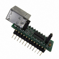
... USB, thus forming the basis of a security dongle which can be used to protect customer application software from being copied. The UM245R is supplied on a PCB which is designed to plug into a standard 15.0mm (0.6”) wide 24 pin DIP socket. All components used, including the FT245RL are Pb-free (RoHS compliant). Figure 1.1 – ...
Page 3
... UM245R Module Circuit Schematic ................................ 22 9 Internal EEPROM Configuration ..................................... 23 10 Contact Information ...................................................... 24 Appendix A – List of Tables and Figures .......................................... 25 Appendix B – Revision History ......................................................... 26 © Copyright 2009 Future Technology Devices International Ltd UM245R USB - Parallel FIFO Development Module Datasheet Version 1.04 Document Reference No.: FT_000202 Clearance No.: FTDI# 124 2 ...
Page 4
... The drivers listed above are all available to download for free from www.ftdichip.com. Various 3rd Party Drivers are also available for other operating systems - visit details. © Copyright 2009 Future Technology Devices International Ltd UM245R USB - Parallel FIFO Development Module Datasheet Version 1.04 Royalty-Free D2XX Direct Drivers (USB Drivers + DLL S/W Interface): Windows 7 32,64-bit ...
Page 5
... Support for bus powered, self powered, and high-power bus powered USB configurations. © Copyright 2009 Future Technology Devices International Ltd UM245R USB - Parallel FIFO Development Module Datasheet Version 1.04 Integrated 3.3V level converter for USB I/O. Integrated level converter on FIFO interface and control pins for interfacing ...
Page 6
... FT245RL Features and Enhancement 3.1 Key Features This section summarises the key features and enhancements of the FT245R IC device which is used in the UM245R Module. For further details, consult the FT245R datasheet, which is available from the FTDI website. Integrated Clock Circuit – Previous generations of FTDI‟s USB to parallel FIFO interface devices required an external crystal or ceramic resonator ...
Page 7
... Both packages are fully compliant with European Union directive 2002/95/EC. © Copyright 2009 Future Technology Devices International Ltd UM245R USB - Parallel FIFO Development Module Datasheet Version 1.04 FTDI website. The FTDIChip-ID is Document Reference No.: FT_000202 Clearance No ...
Page 8
... UM245R Pin Out and Signal Descriptions 4.1 UM245R Pin Out Figure 4.1 Module Pin Out and Jumper Locations © Copyright 2009 Future Technology Devices International Ltd UM245R USB - Parallel FIFO Development Module Datasheet Version 1.04 Document Reference No.: FT_000202 Clearance No.: FTDI# 124 7 ...
Page 9
... Output default configuration). In this case these pins would have the same description as pin 14. To use the UM245R module in a self powered configuration, ensure that jumper J2 pins 1 and 2 are not connected together, and apply an external 3.3V to 5.25V supply to one or both of these pins. ...
Page 10
... This pin is internally connected to the VCC DIP pins. Remove the jumper connector in a self powered design. Table 4.3 Jumper J2 Pin Description © Copyright 2009 Future Technology Devices International Ltd UM245R USB - Parallel FIFO Development Module Datasheet Version 1.04 Document Reference No.: FT_000202 Clearance No.: FTDI# 124 Section 4.4 for timing diagram ...
Page 11
... Valid Data Hold Time from RD# Inactive* T5 RD# Inactive to RXF# T6 RXF# Inactive After RD# Cycle Table 4.4 FIFO Read Cycle Timings * Load = 30pF © Copyright 2009 Future Technology Devices International Ltd UM245R USB - Parallel FIFO Development Module Datasheet Version 1.04 Min Document Reference No.: FT_000202 Clearance No ...
Page 12
... T10 Data Hold Time from RD Inactive T11 WR Inactive to TXE# T12 TXE# Inactive After WR Cycle Table 4.5 FIFO Write Cycle Timings © Copyright 2009 Future Technology Devices International Ltd UM245R USB - Parallel FIFO Development Module Datasheet Version 1.04 Min Document Reference No.: FT_000202 Clearance No ...
Page 13
... Figure 5.1 UM245R Module Dimensions All dimensions are shown in millimeters with inches shown in parenthesis. The FT245RL IC device used by the UM245R is supplied in a RoHS compliant 28 pin SSOP package. The package is lead (Pb) free and uses a „green‟ compound. The date code format is YYXX where digit week number digit year number ...
Page 14
... Current Operating Supply Icc2 Current Table 6.2 Operating Voltage and Current © Copyright 2009 Future Technology Devices International Ltd UM245R USB - Parallel FIFO Development Module Datasheet Version 1.04 Value -65 to +150 168 Hours (IPC/JEDEC J-STD-033A MSL Level 3 Compliant)* -40 to +85 -0.5 to +6.00 -0 ...
Page 15
... Input Switching VHys Hysteresis Table 6.5 FIFO Interface and Control Bus Pin Characteristics (VCCIO = 2.8V, Standard Drive Level) © Copyright 2009 Future Technology Devices International Ltd UM245R USB - Parallel FIFO Development Module Datasheet Version 1.04 Minimum Typical Maximum 3.2 4.1 0.3 ...
Page 16
... Description Input Switching Vin Threshold Input Switching VHys Hysteresis Table 6.9 RESET# and TEST Pin Characteristics © Copyright 2009 Future Technology Devices International Ltd UM245R USB - Parallel FIFO Development Module Datasheet Version 1.04 Minimum Typical Maximum 3.2 4.1 0.3 0.4 1.3 1 ...
Page 17
... The internal 1024 bit EEPROM has the following reliability characteristics: Parameter Value Data Retention 15 Read / Write Cycle 100,000 Table 6.11 EEPROM Characteristics © Copyright 2009 Future Technology Devices International Ltd UM245R USB - Parallel FIFO Development Module Datasheet Version 1.04 Maximu Minimum Typical 2.8 --- 0 --- 0.8 --- 0 ...
Page 18
... Clock Period Duty Cycle Table 6.12 Internal Clock Characteristics NOTE: Use of the internal clock requires VCC the range of 4.0V to 5.25V. © Copyright 2009 Future Technology Devices International Ltd UM245R USB - Parallel FIFO Development Module Datasheet Version 1.04 Value Minimum Typical 11.98 12 ...
Page 19
... Figure 7.1 illustrates the UM245R in a typical USB bus powered design configuration. This can easily be done by fitting the jumper link on J2, as shown above. The UM245R is supplied in this configuration by default. A USB Bus Powered device gets its power from the USB bus. Basic rules for USB Bus power ...
Page 20
... Self Powered Configuration Figure 7.2 Self-Powered Configuration Figure 7.2 illustrates the UM245R in a typical USB self powered configuration. In this case the link on jumper J2 is removed, and an external supply is connected to the module VCC pins. Figure 7.2 illustrate a design which has a 4. supply. ...
Page 21
... VCCIO from the 3V3OUT pin of the FT245R. © Copyright 2009 Future Technology Devices International Ltd UM245R USB - Parallel FIFO Development Module Datasheet Version 1.04 Document Reference No.: FT_000202 Clearance No.: FTDI# 124 ...
Page 22
... The FT245R‟s VCCIO pin is either supplied with 5V from the USB bus (connect together pins 2 and 3 on J1), or with 3.3V from the FT245R‟s 3V3OUT pin (connect together pins 1 and shown). The supply to UM245R‟s 3V3 pin can also be used to supply up to 50mA to external logic. ...
Page 23
... UM245R Module Circuit Schematic Figure 8.1 Module Circuit Schematic © Copyright 2009 Future Technology Devices International Ltd UM245R USB - Parallel FIFO Development Module Datasheet Version 1.04 Document Reference No.: FT_000202 Clearance No.: FTDI# 124 22 ...
Page 24
... Following a power-on reset or a USB reset the FT245R will scan its internal EEPROM and read the USB configuration descriptors stored there. The default values programmed into the internal EEPROM in the FT245RL used on the UM245R are shown in Table 9.1. Parameter USB Vendor ID (VID) ...
Page 25
... Please visit the Sales Network page of the FTDI Web site for the contact details of our distributor(s) and sales representative(s) in your country. © Copyright 2009 Future Technology Devices International Ltd UM245R USB - Parallel FIFO Development Module Datasheet Version 1.04 Document Reference No.: FT_000202 Clearance No.: FTDI# 124 ...
Page 26
... Table 6.11 EEPROM Characteristics ........................................................................................................... 16 Table 6.12 Internal Clock Characteristics .................................................................................................. 17 Table 9.1 Default Internal EEPROM Configuration ..................................................................................... 23 List of Table Figure 1.1 – UM245R USB to Parallel FIFO Development Module ................................................................. 1 Figure 4.1 Module Pin Out and Jumper Locations ........................................................................................ 7 Figure 4.2 FIFO Read Cycle ........................................................................................................................ 10 Figure 4.3 FIFO Write Cycle ....................................................................................................................... 11 Figure 5 ...
Page 27
... Corrected table 4.1- pin 5 DB5 changed to DB1 Updated formatting Added 4.0V VCC/Internal Clock requirement Corrected figures 4.1 and 7.2 © Copyright 2009 Future Technology Devices International Ltd UM245R USB - Parallel FIFO Development Module Datasheet Version 1.04 Document Reference No.: FT_000202 Clearance No.: FTDI# 124 December 2005 December 2005 ...