AC164335 Microchip Technology, AC164335 Datasheet - Page 139
AC164335
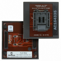
Manufacturer Part Number
AC164335
Description
MODULE SKT FOR 10X10 PM3 44TQFP
Manufacturer
Microchip Technology
Datasheet
1.AC164335.pdf
(286 pages)
Specifications of AC164335
Module/board Type
Socket Module - TQFP
Product
Microcontroller Accessories
Lead Free Status / RoHS Status
Not applicable / Not applicable
For Use With/related Products
MPLAB® PM3
For Use With
DV007003 - PROGRAMMER UNIVERSAL PROMATE II
Lead Free Status / RoHS Status
Lead free / RoHS Compliant, Not applicable / Not applicable


12.34 APPLICATION EXAMPLES:
12.34.1 STANDARD PWM MODE
In standard PWM mode, the PWM output is typically
connected to a single transistor, which charges an
inductor, as shown in Figure 12-22. Buck and Boost
converters typically use standard PWM mode.
FIGURE 12-22:
© 2006 Microchip Technology Inc.
PWM1H
+V
+V
IN
PWM1H
IN
PWM1H
T
Inductor charges during T
ON
L1
versus Period controls power flow
T
ON
APPLICATIONS OF
STANDARD PWM MODE
Boost Converter
Buck Converter
Period
L1
T
OFF
ON
V
+
OUT
+
V
OUT
Preliminary
12.34.2 APPLICATION OF COMPLEMENTARY
Complementary mode PWM is often used in circuits
that use two transistors in a bridge configuration where
transformers are not used, as shown in Figure 12-23.
If transformers are used, then some means must be
provided to ensure that no net DC currents flow
through the transformer to prevent core saturation.
FIGURE 12-23:
PWM1H
PWM1L
+V
dsPIC30F1010/202X
IN
PWM1L
PWM1H
+V
PWM1H
IN
PWM MODE
Dead Time
Synchronous Buck Converter
Series Resonant Half Bridge Converter
PWM1L
C
R
APPLICATIONS OF
COMPLEMENTARY PWM
MODE
Period
L
Dead Time
R
T1
DS70178C-page 137
L1
Dead Time
V
OUT
+
V
+
OUT
Related parts for AC164335
Image
Part Number
Description
Manufacturer
Datasheet
Request
R

Part Number:
Description:
Manufacturer:
Microchip Technology Inc.
Datasheet:
Part Number:
Description:
Manufacturer:
Microchip Technology Inc.
Datasheet:
Part Number:
Description:
Manufacturer:
Microchip Technology Inc.
Datasheet:
Part Number:
Description:
Manufacturer:
Microchip Technology Inc.
Datasheet:
Part Number:
Description:
Manufacturer:
Microchip Technology Inc.
Datasheet:
Part Number:
Description:
Manufacturer:
Microchip Technology Inc.
Datasheet:
Part Number:
Description:
Manufacturer:
Microchip Technology Inc.
Datasheet:
Part Number:
Description:
Manufacturer:
Microchip Technology Inc.
Datasheet: