TWR-LCD Freescale Semiconductor, TWR-LCD Datasheet - Page 8
TWR-LCD
Manufacturer Part Number
TWR-LCD
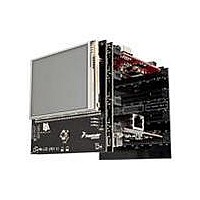
Description
LCD MODULE FOR TWR SYSTEM
Manufacturer
Freescale Semiconductor
Specifications of TWR-LCD
Accessory Type
LCD Display
Product
Microcontroller Modules
Data Bus Width
32 bit
Core Processor
MCF51JM
Interface Type
USB, I2C, SPI
Operating Supply Voltage
5 V
Silicon Manufacturer
Freescale
Core Architecture
Coldfire
Core Sub-architecture
Coldfire V1
Silicon Core Number
MCF51
Silicon Family Name
Flexis - MCF51AC, MCF521x, MCF5301x
Rohs Compliant
Yes
For Use With/related Products
Freescale Tower System
Lead Free Status / RoHS Status
Lead free / RoHS Compliant


(KBEDG7=0) for KBI functionality. Refer to the MCF51JM128 Reference Manual, Section 9, for
additional details. The SD Card Detect signal must be configured as an internal pull‐up regardless of
which host MCU is accessing the MicroSD Card slot.
3.4 5way Navigation Switch
The TWR‐LCD features a 5‐way Navigation Switch. This switch will allow user interaction with the TWR‐
LCD providing a method to indicate Up (North), Down (South), Right (East), Left (West), and Select
(Center). The corresponding directional signals are connected to the on‐board MCF51JM MCU. It is
intended that the on‐board MCF51JM MCU firmware either respond directly to the Navigation Switch
or relay the signal detection to the Tower MCU module through the I2C interface.
It is possible to connect the 5‐way Navigation Switch directly to the Tower Elevator by making a
hardware modification to the TWR‐LCD.
The following resister will should to be populated to create a direct connection to the Tower Elevator:
R19, R22, R23, R24, R26, R28, R29, R32, R41, R44
The resisters are intentionally unpopulated in the final design to ensure maximum compatibility with
additional Freescale Tower MCU and Peripheral Modules.
Populating these resisters will enable to following connections:
Refer to the “Optional Nav Switch Connections to Elevator” section within the TWR‐LCD schematics for
additional details.
3.5 MiniB USB Connection
The TWR‐LCD features a Mini‐B USB connection on the lower right corner of the module. The USB
connector is used to provide power to the TWR‐LCD module when operating in stand‐alone mode (not
connected to the tower system). The USB data signals are connected to the on‐board MCF51JM MCU
allow a connection to exist between a host device and the TWR‐LCD.
In Boot Loader mode, if the USB cable is connected to a host PC, the TWR‐LCD will enumerate as a
Mass Storage Device. If an appropriate compiled binary (.s19) file is placed in the root directory of the
enumerated storage drive, the TWR‐LCD will parse the binary file and reprogram the main application
running on the TWR‐LCD. Refer to Section 3.6 for more details.
Navigation Direction
Select (Center)
Down (South)
Right (East)
Left (West)
Up (North)
TWR‐LCD User’s Manual
Tower Elevator Connection
GPIO7 (Pin A11)
GPIO8 (Pin A10)
GPIO5 (Pin B52)
GPIO1 (Pin B21)
GPIO9 (Pin A9)
Page 8 of 13
Related parts for TWR-LCD
Image
Part Number
Description
Manufacturer
Datasheet
Request
R

Part Number:
Description:
TWR-K53N512 Dev Kit
Manufacturer:
Freescale Semiconductor
Datasheet:
Part Number:
Description:
K53N512CMD100 TWR Module
Manufacturer:
Freescale Semiconductor
Datasheet:

Part Number:
Description:
TOWER ELEVATOR BOARDS HARDWARE
Manufacturer:
Freescale Semiconductor
Datasheet:

Part Number:
Description:
TOWER SERIAL I/O HARDWARE
Manufacturer:
Freescale Semiconductor
Datasheet:

Part Number:
Description:
TOWER SYSTEM BOARD MPC5125
Manufacturer:
Freescale Semiconductor
Datasheet:

Part Number:
Description:
TOWER SYSTEM KIT MPC5125
Manufacturer:
Freescale Semiconductor
Datasheet:

Part Number:
Description:
TOWER SYSTEM BOARD K40X256
Manufacturer:
Freescale Semiconductor
Datasheet:

Part Number:
Description:
TOWER SYSTEM KIT K40X256
Manufacturer:
Freescale Semiconductor
Datasheet:

Part Number:
Description:
MCU, MPU & DSP Development Tools IAR KickStart Kit for Kinetis K60
Manufacturer:
Freescale Semiconductor
Datasheet:

Part Number:
Description:
TOWER SYSTEM PROTO
Manufacturer:
Freescale Semiconductor
Datasheet:
Part Number:
Description:
TOWER SYSTEM KIT MC56F8257
Manufacturer:
Freescale Semiconductor
Datasheet:

Part Number:
Description:
MCU, MPU & DSP Development Tools SERIAL2 TOWER MODULE
Manufacturer:
Freescale Semiconductor
Datasheet:
Part Number:
Description:
TOWER KIT S12G128
Manufacturer:
Freescale Semiconductor
Datasheet:
Part Number:
Description:
TWR SYS Audio Board
Manufacturer:
Freescale Semiconductor
Datasheet:
Part Number:
Description:
TWR-S08UNIV-DEMO Kit
Manufacturer:
Freescale Semiconductor
Datasheet: