TWR-LCD Freescale Semiconductor, TWR-LCD Datasheet - Page 5
TWR-LCD
Manufacturer Part Number
TWR-LCD
Description
LCD MODULE FOR TWR SYSTEM
Manufacturer
Freescale Semiconductor
Specifications of TWR-LCD
Accessory Type
LCD Display
Product
Microcontroller Modules
Data Bus Width
32 bit
Core Processor
MCF51JM
Interface Type
USB, I2C, SPI
Operating Supply Voltage
5 V
Silicon Manufacturer
Freescale
Core Architecture
Coldfire
Core Sub-architecture
Coldfire V1
Silicon Core Number
MCF51
Silicon Family Name
Flexis - MCF51AC, MCF521x, MCF5301x
Rohs Compliant
Yes
For Use With/related Products
Freescale Tower System
Lead Free Status / RoHS Status
Lead free / RoHS Compliant


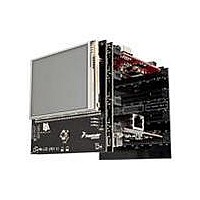
3.2 LCD Display / Controller
The TWR‐LCD features a Truly Semiconductor 3.2” TFT LCD with an analog resistive touch overlay.
3.2.1 Communication Mode
The LCD utilizes a 240 RGB x 320 QVGA display controller. The display controller is accessible to the
on‐board MCF51JM MCU through SPI. The controller is also accessible to any compatible Tower MCU
module through SPI or the External Bus Interface (EBI) via the primary Tower Side Expansion Ports.
Use SW1‐DIP1 and DIP2 to configure the desired interface mode (SPI or EBI). Refer to Section 4 for
more configuration details.
3.2.2 MCU Selection
The LCD can be controlled by either the on‐board MCF51JM MCU or a compatible Tower MCU Module.
Use SW1‐DIP3 to specify which MCU has access to the display controller. Refer to Section 4 for more
configuration details.
Setting the JM/ELE (SW1‐DIP3) configuration switch to the “Off” position will isolate the SPI signals
from the Tower MCU allowing a direct connection between the on‐board MCF51JM MCU and the LCD
display controller.
Setting the JM/ELE configuration switch to the “On” position will cause both the on‐board MCF51JM
MCU and Tower MCU SPI signals to be simultaneously connected to the LCD display controller. It is
required that on‐board MCF51JM MCU firmware detect the status of the JM/ELE signal and tri‐state
the on‐board MCF51JM MCU SPI signals.
SW1-DIP1
(SW1-DIP3)
JM/ELE
(PS2)
OFF
ON
ON
SW1-DIP 2
(PS0)
OFF
OFF
ON
ON
ON
Table 1 ‐ LCD Communication Mode Settings
Table 2 ‐ Display Driver MCU Selection
Enables SPI connection from SPI0 of Primary Elevator Connector
Enables SPI connection from on-board MCF51JM MCU
Enables SPI communication mode to the LCD Display; can be
driven by SPI0 on the Primary Elevator or by the on-board
MCF51JM, selectable by JM/ELE (SW1-DIP3)
Enables EBI (16b mode) communication to the LCD Display
This interface is only accessible from the Tower Elevator MCU
Enables EBI (8b mode) communication to the LCD Display
This interface is only accessible from the Tower Elevator MCU
Description
TWR‐LCD User’s Manual
Page 5 of 13
Related parts for TWR-LCD
Image
Part Number
Description
Manufacturer
Datasheet
Request
R

Part Number:
Description:
TWR-K53N512 Dev Kit
Manufacturer:
Freescale Semiconductor
Datasheet:
Part Number:
Description:
K53N512CMD100 TWR Module
Manufacturer:
Freescale Semiconductor
Datasheet:

Part Number:
Description:
TOWER ELEVATOR BOARDS HARDWARE
Manufacturer:
Freescale Semiconductor
Datasheet:

Part Number:
Description:
TOWER SERIAL I/O HARDWARE
Manufacturer:
Freescale Semiconductor
Datasheet:

Part Number:
Description:
TOWER SYSTEM BOARD MPC5125
Manufacturer:
Freescale Semiconductor
Datasheet:

Part Number:
Description:
TOWER SYSTEM KIT MPC5125
Manufacturer:
Freescale Semiconductor
Datasheet:

Part Number:
Description:
TOWER SYSTEM BOARD K40X256
Manufacturer:
Freescale Semiconductor
Datasheet:

Part Number:
Description:
TOWER SYSTEM KIT K40X256
Manufacturer:
Freescale Semiconductor
Datasheet:

Part Number:
Description:
MCU, MPU & DSP Development Tools IAR KickStart Kit for Kinetis K60
Manufacturer:
Freescale Semiconductor
Datasheet:

Part Number:
Description:
TOWER SYSTEM PROTO
Manufacturer:
Freescale Semiconductor
Datasheet:
Part Number:
Description:
TOWER SYSTEM KIT MC56F8257
Manufacturer:
Freescale Semiconductor
Datasheet:

Part Number:
Description:
MCU, MPU & DSP Development Tools SERIAL2 TOWER MODULE
Manufacturer:
Freescale Semiconductor
Datasheet:
Part Number:
Description:
TOWER KIT S12G128
Manufacturer:
Freescale Semiconductor
Datasheet:
Part Number:
Description:
TWR SYS Audio Board
Manufacturer:
Freescale Semiconductor
Datasheet:
Part Number:
Description:
TWR-S08UNIV-DEMO Kit
Manufacturer:
Freescale Semiconductor
Datasheet: