28122 Parallax Inc, 28122 Datasheet - Page 150
28122
Manufacturer Part Number
28122
Description
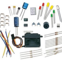
KIT WHAT'S A MICRO:PARTS ONLY
Manufacturer
Parallax Inc
Datasheet
1.28123.pdf
(340 pages)
Specifications of 28122
Accessory Type
Parts Kit
Product
Microcontroller Accessories
Core Processor
PIC16C57c
Flash
128 Bytes
Operating Supply Voltage
9 V
Board Size
31 mm x 16 mm
For Use With/related Products
Board of Education Full Kit
Lead Free Status / RoHS Status
Lead free / RoHS Compliant


Testing the Potentiometer Circuit
How the Potentiometer Circuit Works
The total resistance in your test circuit is 220 Ω plus the resistance between the A and W
terminals of the potentiometer. This value could be anywhere from 0 to 10 kΩ. As you
LED
Vss
√
√
Turn the potentiometer clockwise until it reaches its mechanical limit shown in
Figure 5-6.
Gradually rotate the potentiometer counterclockwise to the positions shown in
Figure 5-6 (b), (c), (d), (e), and (f) noting the how brightly the LED glows at
each position.
Handle with care: If your potentiometer will not turn this far, do not try to force it. Just turn
it until it reaches its mechanical limit; otherwise, it might break.
Vdd
(a)
(b)
nc
220
Pot
10
kΩ
Ω
P15
P14
P13
P12
P11
P10
P9
P8
P7
P6
P5
P4
P3
P2
P1
P0
(c)
(d)
X2
X3
Vdd
Vin
(e)
(f)
Vss
+
Figure 5-6
Potentiometer Input Shaft
(a) through (f) show the
potentiometer’s wiper
terminal set to different
positions.
Figure 5-5
Potentiometer-LED
Test Circuit
Related parts for 28122
Image
Part Number
Description
Manufacturer
Datasheet
Request
R


Part Number:
Description:
Microcontroller Modules & Accessories DISCONTINUED BY PARALLAX
Manufacturer:
Parallax Inc

Part Number:
Description:
BOOK UNDERSTANDING SIGNALS
Manufacturer:
Parallax Inc
Datasheet:


Part Number:
Description:
COMPETITION RING FOR SUMOBOT
Manufacturer:
Parallax Inc
Datasheet:


Part Number:
Description:
TEXT INFRARED REMOTE FOR BOE-BOT
Manufacturer:
Parallax Inc
Datasheet:
Part Number:
Description:
BOARD EXPERIMENT+LCD NX-1000
Manufacturer:
Parallax Inc
Datasheet:

Part Number:
Description:
CONTROLLER 16SERVO MOTOR CONTROL
Manufacturer:
Parallax Inc
Datasheet:

Part Number:
Description:
BASIC STAMP LOGIC ANALYZER
Manufacturer:
Parallax Inc
Datasheet:

Part Number:
Description:
IC MCU 2K FLASH 50MHZ SO-18
Manufacturer:
Parallax Inc
Datasheet: