28122 Parallax Inc, 28122 Datasheet - Page 149
28122
Manufacturer Part Number
28122
Description
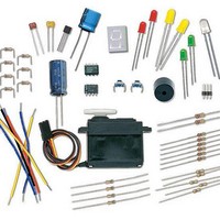
KIT WHAT'S A MICRO:PARTS ONLY
Manufacturer
Parallax Inc
Datasheet
1.28123.pdf
(340 pages)
Specifications of 28122
Accessory Type
Parts Kit
Product
Microcontroller Accessories
Core Processor
PIC16C57c
Flash
128 Bytes
Operating Supply Voltage
9 V
Board Size
31 mm x 16 mm
For Use With/related Products
Board of Education Full Kit
Lead Free Status / RoHS Status
Lead free / RoHS Compliant


ACTIVITY #1: BUILDING AND TESTING THE POTENTIOMETER CIRCUIT
Placing different size resistors in series with an LED causes different amounts of current
to flow through the circuit. Large resistance in the LED circuit causes small amounts of
current to flow through the circuit, and the LED glows dimly. Small resistances in the
LED circuit causes more current to flow through the circuit, and the LED glows more
brightly. By connecting the W and A terminals of the potentiometer, in series with an
LED circuit, you can use it to adjust the resistance in the circuit. This in turn adjusts the
brightness of the LED. In this activity, you will use the potentiometer as a variable
resistor and use it to change the brightness of the LED.
Dial Circuit Parts
(1) Potentiometer – 10 kΩ
(1) Resistor – 220 Ω (red-red-brown)
(1) LED – any color
(1) Jumper wire
Building the Potentiometer Test Circuit
Figure 5-5 shows a circuit that can be used for adjusting the LED’s brightness with a
potentiometer.
√
Build the circuit shown in Figure 5-5.
Tip: Use a needle-nose pliers to straighten the kinks out of the potentiometer’s legs before
plugging the device into the breadboard. When the potentiometer’s legs are straight, they
maintain better contact with the breadboard sockets.
Related parts for 28122
Image
Part Number
Description
Manufacturer
Datasheet
Request
R


Part Number:
Description:
Microcontroller Modules & Accessories DISCONTINUED BY PARALLAX
Manufacturer:
Parallax Inc

Part Number:
Description:
BOOK UNDERSTANDING SIGNALS
Manufacturer:
Parallax Inc
Datasheet:


Part Number:
Description:
COMPETITION RING FOR SUMOBOT
Manufacturer:
Parallax Inc
Datasheet:


Part Number:
Description:
TEXT INFRARED REMOTE FOR BOE-BOT
Manufacturer:
Parallax Inc
Datasheet:
Part Number:
Description:
BOARD EXPERIMENT+LCD NX-1000
Manufacturer:
Parallax Inc
Datasheet:

Part Number:
Description:
CONTROLLER 16SERVO MOTOR CONTROL
Manufacturer:
Parallax Inc
Datasheet:

Part Number:
Description:
BASIC STAMP LOGIC ANALYZER
Manufacturer:
Parallax Inc
Datasheet:

Part Number:
Description:
IC MCU 2K FLASH 50MHZ SO-18
Manufacturer:
Parallax Inc
Datasheet: