AC1059 Analog Devices Inc, AC1059 Datasheet - Page 5
AC1059
Manufacturer Part Number
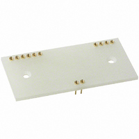
AC1059
Description
SOCKET FOR MODEL AD210 IC
Manufacturer
Analog Devices Inc
Specifications of AC1059
Accessory Type
Mating Socket
Connector Type
DIP Socket
No. Of Contacts
12
Pitch Spacing
2.54mm
Row Pitch
20.32mm
Contact Termination
Through Hole
Socket Mounting
PC Board
Number Of Contacts
12
Primary Type
AD210
Lead Free Status / RoHS Status
Lead free / RoHS Compliant
For Use With/related Products
AD210
Lead Free Status / RoHS Status
Contains lead / RoHS non-compliant, Lead free / RoHS Compliant


Phase Shift: Figure 10 illustrates the AD210’s low phase shift
and gain versus frequency. The AD210’s phase shift and wide
bandwidth performance make it well suited for applications like
power monitors and controls systems.
Input Noise vs. Frequency: Voltage noise referred to the input
is dependent on gain and signal bandwidth. Figure 11 illustrates
the typical input noise in nV/ Hz of the AD210 for a frequency
range from 10 to 10 kHz.
Gain Nonlinearity vs. Output: Gain nonlinearity is defined as the
deviation of the output voltage from the best straight line, and is
specified as % peak-to-peak of output span. The AD210B provides
guaranteed maximum nonlinearity of 0.012% with an output span of
Gain Nonlinearity vs. Output Swing: The gain nonlinearity
of the AD210 varies as a function of total signal swing. When
the output swing is less than 20 volts, the gain nonlinearity as a
fraction of signal swing improves. The shape of the nonlinearity
remains constant. Figure 13 shows the gain nonlinearity of the
AD210 as a function of total signal swing.
REV. A
10 V. The AD210’s nonlinearity performance is shown in Figure 12.
–20
–40
–60
–80
60
40
20
Figure 10. Phase Shift and Gain vs. Frequency
0
10
60
50
40
30
20
10
0
10
Figure 11. Input Noise vs. Frequency
100
FREQUENCY – Hz
100
FREQUENCY – Hz
G = 100
G = 1
1k
10k
1k
100k
0
–20
–40
–60
–80
–100
–120
–140
10k
–5–
Gain vs. Temperature: Figure 14 illustrates the AD210’s
gain vs. temperature performance. The gain versus temperature
performance illustrated is for an AD210 configured as a unity
gain amplifier.
100
+0.04
+0.03
+0.02
+0.01
–0.01
–0.02
–0.03
–0.04
90
80
70
60
50
40
30
20
10
0
Figure 13. Gain Nonlinearity vs. Output Swing
Figure 12. Gain Nonlinearity Error vs. Output
–1000
–1200
–1400
–1600
0
0
–200
–400
–600
–800
400
200
–10
0
–25
2
–8
Figure 14. Gain vs. Temperature
4
–6
TOTAL SIGNAL SWING – Volts
OUTPUT VOLTAGE SWING – Volts
6
–4
0
8
–2
TEMPERATURE – C
10
0
+25
12
+2
14
+4
+50
16
+6
G = 1
18
AD210
+8
+70
20
+10
0.01
0.009
0.008
0.007
0.006
0.005
0.004
0.003
0.002
0.001
0.000
+8
+6
+4
+2
–2
–4
–6
–8
+85
0
Related parts for AC1059
Image
Part Number
Description
Manufacturer
Datasheet
Request
R

Part Number:
Description:
±1.7g Dual-Axis IMEMS Accelerometer Evaluation Board
Manufacturer:
Analog Devices Inc
Datasheet:

Part Number:
Description:
Inertial Sensor Evaluation System
Manufacturer:
Analog Devices Inc
Datasheet:
Part Number:
Description:
Manufacturer:
Analog Devices Inc
Datasheet:
Part Number:
Description:
Manufacturer:
Analog Devices Inc
Datasheet:
Part Number:
Description:
Manufacturer:
Analog Devices Inc
Datasheet:
Part Number:
Description:
Manufacturer:
Analog Devices Inc
Datasheet:
Part Number:
Description:
Manufacturer:
Analog Devices Inc
Datasheet:
Part Number:
Description:
Manufacturer:
Analog Devices Inc
Datasheet:
Part Number:
Description:
Manufacturer:
Analog Devices Inc
Datasheet:
Part Number:
Description:
Manufacturer:
Analog Devices Inc
Datasheet:
Part Number:
Description:
Manufacturer:
Analog Devices Inc
Datasheet:
Part Number:
Description:
Manufacturer:
Analog Devices Inc
Datasheet:
Part Number:
Description:
Manufacturer:
Analog Devices Inc
Datasheet: