AC1059 Analog Devices Inc, AC1059 Datasheet - Page 4
AC1059
Manufacturer Part Number
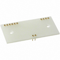
AC1059
Description
SOCKET FOR MODEL AD210 IC
Manufacturer
Analog Devices Inc
Specifications of AC1059
Accessory Type
Mating Socket
Connector Type
DIP Socket
No. Of Contacts
12
Pitch Spacing
2.54mm
Row Pitch
20.32mm
Contact Termination
Through Hole
Socket Mounting
PC Board
Number Of Contacts
12
Primary Type
AD210
Lead Free Status / RoHS Status
Lead free / RoHS Compliant
For Use With/related Products
AD210
Lead Free Status / RoHS Status
Contains lead / RoHS non-compliant, Lead free / RoHS Compliant


AD210
low side of the signal source. This will not work if the source has
another current path to input common or if current flows in the
signal source LO lead. To minimize CMR degradation, keep the
resistor in series with the input LO below a few hundred ohms.
Figure 5 also shows the preferred gain adjustment circuit. The
circuit shows R
greater. The adjustment becomes less effective at lower gains
(its effect is halved at G = 2) so that the pot will have to be a
larger fraction of the total R
the gain cannot be adjusted downward without compromising
input impedance; it is better to adjust gain at the signal source
or after the output.
Figure 6 shows the input adjustment circuit for use when the
input amplifier is configured in the inverting mode. The offset
adjustment nulls the voltage at the summing node. This is pref-
erable to current injection because it is less affected by subse-
quent gain adjustment. Gain adjustment is made in the feedback
and will work for gains from 1 V/V to 100 V/V.
Figure 7 shows how offset adjustments can be made at the out-
put, by offsetting the floating output port. In this circuit, 15 V
would be supplied by a separate source. The AD210’s output
amplifier is fixed at unity, therefore, output gain must be made
in a subsequent stage.
PCB Layout for Multichannel Applications: The unique
pinout positioning minimizes board space constraints for multi-
channel applications. Figure 8 shows the recommended printed
circuit board layout for a noninverting input configuration with
gain.
V
SIG
17
16
19
18
14
15
R
S
50k
+V
–V
47.5k
ISS
ISS
Figure 6. Adjustments for Inverting Input
Figure 7. Output-Side Offset Adjustment
OFFSET
F
200
+15V
of 50 k , and will work for gains of ten or
30
5k
GAIN
100k
29
16
17
19
18
14
15
F
+V
AD210
+V
–V
–V
at low gain. At G = 1 (follower)
ISS
ISS
OSS
OSS
1
4
2
3
+15V
30
200
29
V
OUT
+15V
0.1µF
AD210
+V
–V
50k
OSS
OSS
OFFSET
100k
1
4
2
3
–15V
V
OUT
–4–
Figure 8. PCB Layout for Multichannel Applications with
Gain
Synchronization: The AD210 is insensitive to the clock of an
adjacent unit, eliminating the need to synchronize the clocks.
However, in rare instances channel to channel pick-up may
occur if input signal wires are bundled together. If this happens,
shielded input cables are recommended.
PERFORMANCE CHARACTERISTICS
Common-Mode Rejection: Figure 9 shows the common-
mode rejection of the AD210 versus frequency, gain and input
source resistance. For maximum common-mode rejection of
unwanted signals, keep the input source resistance low and care-
fully lay out the input, avoiding excessive stray capacitance at
the input terminals.
GRID
0.1"
Figure 9. Common-Mode Rejection vs. Frequency
180
160
140
120
100
80
60
40
1
1
10
R
G
20
R
F
CHANNEL OUTPUTS
CHANNEL INPUTS
50 60 100
2
2
FREQUENCY – Hz
R
G
200
R
F
500
3
3
1k
G = 100
G = 1
R
G
R
2k
F
5k
REV. A
10k
POWER
Related parts for AC1059
Image
Part Number
Description
Manufacturer
Datasheet
Request
R

Part Number:
Description:
±1.7g Dual-Axis IMEMS Accelerometer Evaluation Board
Manufacturer:
Analog Devices Inc
Datasheet:

Part Number:
Description:
Inertial Sensor Evaluation System
Manufacturer:
Analog Devices Inc
Datasheet:
Part Number:
Description:
Manufacturer:
Analog Devices Inc
Datasheet:
Part Number:
Description:
Manufacturer:
Analog Devices Inc
Datasheet:
Part Number:
Description:
Manufacturer:
Analog Devices Inc
Datasheet:
Part Number:
Description:
Manufacturer:
Analog Devices Inc
Datasheet:
Part Number:
Description:
Manufacturer:
Analog Devices Inc
Datasheet:
Part Number:
Description:
Manufacturer:
Analog Devices Inc
Datasheet:
Part Number:
Description:
Manufacturer:
Analog Devices Inc
Datasheet:
Part Number:
Description:
Manufacturer:
Analog Devices Inc
Datasheet:
Part Number:
Description:
Manufacturer:
Analog Devices Inc
Datasheet:
Part Number:
Description:
Manufacturer:
Analog Devices Inc
Datasheet:
Part Number:
Description:
Manufacturer:
Analog Devices Inc
Datasheet: