TWR-MEM Freescale Semiconductor, TWR-MEM Datasheet - Page 6
TWR-MEM
Manufacturer Part Number
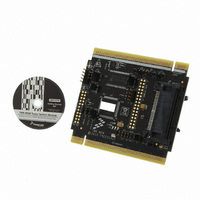
TWR-MEM
Description
MEMORY MODULE FOR TWR SYSTEM
Manufacturer
Freescale Semiconductor
Specifications of TWR-MEM
Accessory Type
Memory Extension Card
Product
Microcontroller Modules
Data Bus Width
8 bit
Interface Type
JTAG, SPI
Flash
1 MB
Operating Supply Voltage
3.3 V
Silicon Manufacturer
Freescale
Core Architecture
Coldfire
Core Sub-architecture
Coldfire V1, Coldfire V2, Coldfire V3
Silicon Core Number
MCF51, MCF52, MCF53
Rohs Compliant
Yes
For Use With/related Products
Freescale Tower System
Lead Free Status / RoHS Status
Lead free / RoHS Compliant


The TWR-MEM SD Card interface implements several configuration options to make it as flexible as
possible. Refer to Table 3 for a complete list of the options.
When using SPI mode to communicate with the SD Card interface, the SPI chip-select can be
configured using J3 to select between SPI1_CS1 and SPI1_CS0.
The SD Card Detect signal can be connected to IRQ_A and/or IRQ_H by placing a jumper shunt on
J12[3:4] and/or J12[1:2], respectively. This will allow the host controller to monitor the presence of an
SD memory or I/O card.
3.5 CompactFlash
The CompactFlash slot on the TWR-MEM can accept Type I (3.3mm thick) CF cards or PC Cards in the
CompactFlash form factor. The CompactFlash slot is connected to the External Bus Interface (EBI) on
the Primary Elevator Connector. An 8-bit data bus is implemented using EBI_D[7:0]. The necessary
address and control signals are routed from the EBI and through a CPLD. This allows for the
implementation of any glue logic that may be required depending on the protocol of the EBI of the
host controller. Refer to Section 3.6 for details on the CPLD.
3.6 CPLD
TWR-MEM features an Altera Max II CPLD. Its primary purpose is to provide any interface logic
required between the EBI and the CompactFlash slot. However, many of the IOs of the CPLD are also
brought out to expansion headers for easy access when the CPLD is reprogrammed by the user for
alternate purposes. Consult the schematics for details on the pinouts of the CPLD including the J7 and
J9 expansion connectors.
Elevator
Pin #
B10
B11
B22
B52
A10
A11
B7
B8
B9
SDHC_CMD / SPI1_MOSI
SDHC_D3 / SPI1_CS1_b
SDHC_D3 / SPI1_CS0_b
GPIO5 / SD_CARD_DET
SDHC_D0 / SPI1_MISO
SDHC_CLK / SPI1_CLK
GPIO7 / SD_WP_DET
GPIO2 / SDHC_D1
GPIO8 / SDHC_D2
Name
Table 1. Tower System SD Card Interface Pinout
GPIO / SDHC
GPIO / SDHC
GPIO / SDHC
GPIO / SDHC
SDHC / SPI 1
SDHC / SPI 1
SDHC / SPI 1
SDHC / SPI 1
SDHC / SPI 1
TWR-MEM User’s Manual
Group
SDHC or SPI Clock
SDHC Chip Select / Data or SPI Chip Select
SDHC Chip Select / Data or SPI Chip Select
SDHC Command or SPI Master Out / Slave In
SDHC Data or SPI Master In / Slave Out
General Purpose I/O or SDHC Data
General Purpose I/O
General Purpose I/O or SDHC Data
General Purpose I/O or SD Function
Description
Page 6 of 11
I/O
I/O
I/O
I/O
I/O
O
O
O
O
I
Related parts for TWR-MEM
Image
Part Number
Description
Manufacturer
Datasheet
Request
R

Part Number:
Description:
TWR-K53N512 Dev Kit
Manufacturer:
Freescale Semiconductor
Datasheet:

Part Number:
Description:
LCD MODULE FOR TWR SYSTEM
Manufacturer:
Freescale Semiconductor
Datasheet:
Part Number:
Description:
K53N512CMD100 TWR Module
Manufacturer:
Freescale Semiconductor
Datasheet:

Part Number:
Description:
TOWER ELEVATOR BOARDS HARDWARE
Manufacturer:
Freescale Semiconductor
Datasheet:

Part Number:
Description:
TOWER SERIAL I/O HARDWARE
Manufacturer:
Freescale Semiconductor
Datasheet:

Part Number:
Description:
TOWER SYSTEM BOARD MPC5125
Manufacturer:
Freescale Semiconductor
Datasheet:

Part Number:
Description:
TOWER SYSTEM KIT MPC5125
Manufacturer:
Freescale Semiconductor
Datasheet:

Part Number:
Description:
TOWER SYSTEM BOARD K40X256
Manufacturer:
Freescale Semiconductor
Datasheet:

Part Number:
Description:
TOWER SYSTEM KIT K40X256
Manufacturer:
Freescale Semiconductor
Datasheet:

Part Number:
Description:
MCU, MPU & DSP Development Tools IAR KickStart Kit for Kinetis K60
Manufacturer:
Freescale Semiconductor
Datasheet:

Part Number:
Description:
TOWER SYSTEM PROTO
Manufacturer:
Freescale Semiconductor
Datasheet:
Part Number:
Description:
TOWER SYSTEM KIT MC56F8257
Manufacturer:
Freescale Semiconductor
Datasheet:

Part Number:
Description:
MCU, MPU & DSP Development Tools SERIAL2 TOWER MODULE
Manufacturer:
Freescale Semiconductor
Datasheet:
Part Number:
Description:
TOWER KIT S12G128
Manufacturer:
Freescale Semiconductor
Datasheet:
Part Number:
Description:
TWR SYS Audio Board
Manufacturer:
Freescale Semiconductor
Datasheet: