STEVAL-ILL025V1 STMicroelectronics, STEVAL-ILL025V1 Datasheet - Page 16
STEVAL-ILL025V1
Manufacturer Part Number
STEVAL-ILL025V1
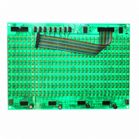
Description
LED MATRIX DISPLAY PANEL
Manufacturer
STMicroelectronics
Datasheets
1.STP16DP05TTR.pdf
(31 pages)
2.STEVAL-ILL025V1.pdf
(30 pages)
3.STEVAL-ILL025V1.pdf
(4 pages)
Specifications of STEVAL-ILL025V1
Design Resources
STEVAL-ILL025V1 BOM STEVAL-ILL025V1 Schematic
Accessory Type
Daughter Board
Description/function
LED Demo System Display Unit
Product
Display Modules
Software
Software Included
For Use With/related Products
*
Lead Free Status / RoHS Status
Lead free / RoHS Compliant
Other names
497-9087
Available stocks
Company
Part Number
Manufacturer
Quantity
Price
Company:

Part Number:
STEVAL-ILL025V1
Manufacturer:
STMicroelectronics
Quantity:
1


System operation modes
16/30
Steps:
●
●
●
●
●
●
●
●
●
●
●
●
Connect a serial cable between the serial port of the computer and the female DB9
connector of the master control unit (VB1).
Connect the PS2 keyboard to the master control unit.
Configure the HyperTerminal on the computer using the following settings:
–
–
–
–
–
Configure the ASCII settings as shown in
Power-up the master control unit, the LED panel and also the slave control unit (if
connected).
The LCD on the master displays the menu program which shows “Press F1 for PC-
UARTComm”.
Press the F1 key on the keyboard attached to the PS2 connector of the master control
unit.
The HyperTerminal shows the message
–
–
Enter the slave control unit address (as seen on the LCD of the slave control unit) or
the address of the master (255), and then press the “Enter” key on the PC keyboard.
Addresses allowed are between 1 and 255.
If the entered address is not present there is an error message on the HyperTerminal,
“Address Mismatch; enter display board address”. Check the address of the slave
board and then re-enter it on the HyperTerminal.
When the address is matched, the message on the HyperTerminal is “Enter no. of LED
boards”. Enter the number of LED display panels connected in cascade to the selected
control unit (one LED display panel constitutes 16x32 LED's). A maximum of 8 panels
can be connected to any one control unit.
The next message is “enter mode; Entr between 1-9”. This is for entering one of the 9
display modes. These are the following:
–
–
–
–
–
–
–
–
–
Bits per second: 115200
DataBits: 8
Parity: none
Stop bits: 1
Flow control: none
“USART HyperTerminal communication demo maximum allowed string length is
200 Words”
“Enter display board address, Enter 1-255”
Mode 1 => curtain up
Mode 2 => curtain down
Mode 3 = > left to right scroll
Mode 4 => right to left scroll
Mode 5 => typing data mode
Mode 6 => stable display
Mode 7 => flashing mode
Mode 8 => curtain right
Mode 9 => curtain left
Doc ID 16147 Rev 1
Figure
9.
UM0767
Related parts for STEVAL-ILL025V1
Image
Part Number
Description
Manufacturer
Datasheet
Request
R

Part Number:
Description:
BOARD EVAL FOR MEMS SENSORS
Manufacturer:
STMicroelectronics
Datasheet:

Part Number:
Description:
KIT DEV STARTER ST10F276Z5
Manufacturer:
STMicroelectronics
Datasheet:

Part Number:
Description:
BOARD EVAL HDMI $ VIDEO SWITCH
Manufacturer:
STMicroelectronics
Datasheet:

Part Number:
Description:
BOARD DEMO ACCELEROMETER DIL24
Manufacturer:
STMicroelectronics
Datasheet:

Part Number:
Description:
BOARD STLM75/STDS75/ST72F651
Manufacturer:
STMicroelectronics
Datasheet:

Part Number:
Description:
EVAL BOARD 3AXIS MEMS ACCELLRMTR
Manufacturer:
STMicroelectronics
Datasheet:

Part Number:
Description:
BOARD EVAL 8BIT MICRO + TDE1708
Manufacturer:
STMicroelectronics
Datasheet:

Part Number:
Description:
EVAL BOARD A/D TS4657
Manufacturer:
STMicroelectronics
Datasheet:

Part Number:
Description:
BOARD ADAPTER 20DIP LIS3LV02DL
Manufacturer:
STMicroelectronics
Datasheet:

Part Number:
Description:
BOARD DEMO STM8S207R6/LIS331DLH
Manufacturer:
STMicroelectronics
Datasheet:

Part Number:
Description:
STMicroelectronics [RIPPLE-CARRY BINARY COUNTER/DIVIDERS]
Manufacturer:
STMicroelectronics
Datasheet:
Part Number:
Description:
STMicroelectronics [LIQUID-CRYSTAL DISPLAY DRIVERS]
Manufacturer:
STMicroelectronics
Datasheet:
Part Number:
Description:
BOARD EVAL FOR MEMS SENSORS
Manufacturer:
STMicroelectronics
Datasheet: