ATSTK524 Atmel, ATSTK524 Datasheet - Page 3
ATSTK524
Manufacturer Part Number
ATSTK524
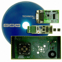
Description
KIT STARTER ATMEGA32M1/MEGA32C1
Manufacturer
Atmel
Datasheet
1.ATSTK524.pdf
(20 pages)
Specifications of ATSTK524
Accessory Type
Daughter Board
For Use With/related Products
STK500
For Use With
ATSTK500 - PROGRAMMER AVR STARTER KIT
Lead Free Status / RoHS Status
Lead free / RoHS Compliant


3. Using the STK524 Top Module
3.1
Figure 3-1.
3.1.1
7780A–AVR–02/08
Connecting the STK524 to the STK500 Starter Kit
Placing a ATmega32M1 or ATmega32C1 on the STK524
Connecting STK524 to the STK500 Board
Connect the STK524 to the STK500 expansion header 0 and 1. It is important that the top mod-
ule is connected in the correct orientation as shown in
STK524 top module should match the EXPAND0 written beside the expansion header on the
STK500 board.
Note:
The STK524 contains a ZIF socket for a TQFP32 package. Care should be taken so that the
device is mounted with the correct orientation.
socket.
Connecting the STK524 with wrong orientation may damage the board.
Figure 3-2
Figure
shows the location of pin1 for the ZIF
3-1. The EXPAND0 written on the
AVR078
3
Related parts for ATSTK524
Image
Part Number
Description
Manufacturer
Datasheet
Request
R

Part Number:
Description:
DEV KIT FOR AVR/AVR32
Manufacturer:
Atmel
Datasheet:

Part Number:
Description:
INTERVAL AND WIPE/WASH WIPER CONTROL IC WITH DELAY
Manufacturer:
ATMEL Corporation
Datasheet:
Part Number:
Description:
Low-Voltage Voice-Switched IC for Hands-Free Operation
Manufacturer:
ATMEL Corporation
Datasheet:
Part Number:
Description:
MONOLITHIC INTEGRATED FEATUREPHONE CIRCUIT
Manufacturer:
ATMEL Corporation
Datasheet:
Part Number:
Description:
AM-FM Receiver IC U4255BM-M
Manufacturer:
ATMEL Corporation
Datasheet:
Part Number:
Description:
Monolithic Integrated Feature Phone Circuit
Manufacturer:
ATMEL Corporation
Datasheet:
Part Number:
Description:
Multistandard Video-IF and Quasi Parallel Sound Processing
Manufacturer:
ATMEL Corporation
Datasheet:
Part Number:
Description:
High-performance EE PLD
Manufacturer:
ATMEL Corporation
Datasheet:
Part Number:
Description:
8-bit Flash Microcontroller
Manufacturer:
ATMEL Corporation
Datasheet:
Part Number:
Description:
2-Wire Serial EEPROM
Manufacturer:
ATMEL Corporation
Datasheet: