ATSTK524 Atmel, ATSTK524 Datasheet
ATSTK524
Specifications of ATSTK524


Related parts for ATSTK524


ATSTK524 Summary of contents
Page 1
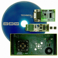
... Introduction The STK524 kit is made of the STK524 board, AVRCANAdapt and AVRLINAdapt boards. The STK524 board is a top module for the STK500 development board from Atmel Corporation designed to support the ATmega32M1, ATmega32C1 products and future compatible derivatives. AVRCANAdapt is a hardware driver for CAN network featuring the Atmel AT6660 CAN driver while the AVRLINAdapt is the hardware driver for LIN, featuring the Atmel AT6661 LIN driver ...
Page 2
Figure 1-1. STK524 Top Module for STK500 with LIN & CAN buses adapters 2. Features • STK524 is a New Member of the Successful STK500 Starter Kit Family. • Supports the ATmega32M1 and ATmega32C1. • CAN Interface thru Port using ...
Page 3
Using the STK524 Top Module 3.1 Connecting the STK524 to the STK500 Starter Kit Connect the STK524 to the STK500 expansion header 0 and important that the top mod- ule is connected in the correct orientation ...
Page 4
Figure 3-2. Caution: Do not mount a ATmega32M1 or ATmega32C1 on the STK524 at the same time as an AVR is mounted on the STK500 board. None of the devices might work as intended. 3.2 AVRLINAdapt & AVRCANAdapt description LIN ...
Page 5
AVRCANAdapt See STK501CAN extension user’s guide for more detailed information Figure 3-4. CAN bus adapter. 3.3 Connecting the AVRLINAdapt & AVRCANAdapt to STK524 LIN bus & CAN bus are accessible thru the add-on boards provided in the kit : ...
Page 6
Figure 3-5. Connecting AVRLINAdapt & AVRCANAdapt to STK524 CAN network LIN network Note recommended to mount a 8 MHz crystal when using CAN interface on the STK524. AVR078 6 LIN network CAN network 7780A–AVR–02/08 ...
Page 7
Programming the AVR The AVR (ATmega32M1, ATmega32C1) can be programmed using both serial SPI and High- voltage Parallel Programming. This section will explain how to connect the programming cables to successfully use one of these two modes. The AVR ...
Page 8
Table 4-1. Note: Note: 4.2 High-voltage Programming Figure 4-2. AVR078 8 In-System programming jumper settings for ATmega32M1/C1 STK500 VTARGET AREF RESET XTAL1 OSCSEL BSEL2 PJUMP STK524 VTG See STK500 User Guide for information on how to use the STK500 front-end ...
Page 9
To program the AVR using High-voltage (Parallel) Programming, connect the PROGCTRL to PORTD and PROGDATA to PORTB on the STK500 as shown in TOSC-switch is placed in the XTAL position. The STK500 & STK524 jumpers must follow the configuration : ...
Page 10
... The ISP connector is used for the ATmega32M1/C1 built-in debugWire interface. The pin out of the connector is shown in from Atmel. Connecting a JTAGICE mkII to this connector allows On-chip Debugging of the ATmega32M1/C1. More information about the JTAGICE mkII and On-chip Debugging can be found in the AVR JTAGICE mkII User Guide, which is available at the Atmel web site, www ...
Page 11
Note: 4.4 STK524 Jumpers, Leds & Test Points Table 4-3. Jumper JP1 JP2 JP3 JP4 JP5 JP6 (1) : Let it opened if the address resistor of the AVRLINAdapt is selected.See on page 4 Table 4-4. Test Point T1 T2 ...
Page 12
Potentiometer The STK524 includes a potentiometer. To use the potentiometer, please mount JP4 and use JP5.2 line as Potentiometer output. The potentiometer is supplied by AREF and it delivers a voltage to JP5.2. This line can be con- nected ...
Page 13
... Technical Support For Technical support, please contact avr@atmel.com. When requesting technical support, please include the following information: • Which target AVR device is used (complete part number). • Target voltage and speed. • Clock source and fuse setting of the AVR. • Programming method (ISP or High-voltage). ...
Page 14
Figure 6-1. Schematics AVR078 14 7780A–AVR–02/08 ...
Page 15
Figure 6-2. Schematics 7780A–AVR–02/08 AVR078 15 ...
Page 16
Figure 6-3. Schematics AVR078 16 PC7 PB2 25 16 PB5 PD7 26 15 PB6 PD6 27 14 PB7 PD5 28 13 PD0 PD4 29 12 PC0 PE2 30 11 PE0 PE1 31 10 PD1 PB1 32 9 ...
Page 17
Figure 6-4. Schematics 7780A–AVR–02/ PC7 25 PB5 26 PB6 27 PB7 28 PD0 29 PC0 30 PE0 31 PD1 32 PB2 16 PD7 15 PD6 14 PD5 13 PD4 12 PE2 11 PE1 ...
Page 18
Figure 6-5. ATAVRLINADAPT AVR078 7780A–AVR–02/08 ...
Page 19
Figure 6-6. STK501 CAN Add On 7780A–AVR–02/ CTRL OFF AVR078 ...
Page 20
... Disclaimer: The information in this document is provided in connection with Atmel products. No license, express or implied, by estoppel or otherwise, to any intellectual property right is granted by this document or in connection with the sale of Atmel products. EXCEPT AS SET FORTH IN ATMEL’S TERMS AND CONDI- TIONS OF SALE LOCATED ON ATMEL’S WEB SITE, ATMEL ASSUMES NO LIABILITY WHATSOEVER AND DISCLAIMS ANY EXPRESS, IMPLIED OR STATUTORY WARRANTY RELATING TO ITS PRODUCTS INCLUDING, BUT NOT LIMITED TO, THE IMPLIED WARRANTY OF MERCHANTABILITY, FITNESS FOR A PARTICULAR PURPOSE, OR NON-INFRINGEMENT ...