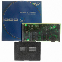
ATSTK520 Atmel, ATSTK520 Datasheet - Page 10

ATSTK520
Manufacturer Part Number
ATSTK520
Description
ADAPTER KIT FOR 90PWM
Manufacturer
Atmel
Datasheet
1.ATSTK520.pdf
(24 pages)
Specifications of ATSTK520
Accessory Type
STK500 Expansion Module
Silicon Manufacturer
Atmel
Core Architecture
AVR
Silicon Core Number
AT90PWM2, AT90PWM3
Kit Contents
Board Cable Docs
Rohs Compliant
Yes
For Use With/related Products
24-Pin and 32-Pin AT90PWM AVR Devices
For Use With
ATSTK500 - PROGRAMMER AVR STARTER KIT
Lead Free Status / RoHS Status
Lead free / RoHS Compliant
Available stocks
Company
Part Number
Manufacturer
Quantity
Price
Company:
Part Number:
ATSTK520
Manufacturer:
Atmel
Quantity:
135
7510A–AVR–08/05
Using the STK520 Top Module
2.3
2-9
JTAGICE mkII
Connector
See the following document :
“JTAGICE mkII Quick Start Guide” which purpose is “Connecting to a target board with
the AVR JTAGICE mkII”.
This note explains which signals are required for ISP and which signals are required for
debugWIRE.
Figure 2-6 shows how to connect the JTAGICE mkII probe on the STK520 board.
Figure 2-6. Connecting JTAG ICE to the STK520
The ISP connector is used for the AT90PWM3 built-in debugWire interface. The pin out
of the connector is shown in Table 2-1 and is compliant with the pin out of the JTAG ICE
available from Atmel. Connecting a JTAG ICE to this connector allows On-chip Debug-
ging of the AT90PWM3.
More information about the JTAG ICE and On-chip Debugging can be found in the AVR
JTAG ICE User Guide, which is available at the Atmel web site, www.atmel.com.
STK520 User Guide


