MA180021 Microchip Technology, MA180021 Datasheet - Page 19
MA180021
Manufacturer Part Number
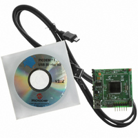
MA180021
Description
MODULE PLUG-IN 18F87J50 FS USB
Manufacturer
Microchip Technology
Series
PIC®r
Specifications of MA180021
Accessory Type
Plug-In Module (PIM) - PIC18F87J50
Silicon Manufacturer
Microchip
Core Architecture
PIC
Core Sub-architecture
PIC18
Features
Full Speed USB Demonstration, Operated Either Stand Alone Or As Plug-In Module
Silicon Core Number
PIC18F
Silicon Family Name
PIC18FxxJxx
Lead Free Status / RoHS Status
Lead free / RoHS Compliant
For Use With/related Products
HPC Explorer Board (DM183022) or PIC18 Explorer Board (DM183032)
For Use With
DM183032 - BOARD EXPLORER PICDEM PIC18DM183022 - BOARD DEMO PIC18FXX22 64/80TQFP
Lead Free Status / RoHS Status
Lead free / RoHS Compliant
Available stocks
Company
Part Number
Manufacturer
Quantity
Price
Company:

Part Number:
MA180021
Manufacturer:
Microchip Technology
Quantity:
135


3.8
© 2007 Microchip Technology Inc.
HARDWARE CONSIDERATIONS FOR COMPLIANCE TESTING
Self-powered peripherals should periodically monitor the +5V V
when it is driven high. Only when it is powered should user firmware enable the USB
module and turn on the D+ (for full speed) or D- (for low speed) pull-up resistor, signal-
ing device attach to the host. The recommended method of monitoring the +5V V
line is to connect it to one of the microcontroller’s 5.5V tolerant I/O pins through a large
value resistor (such as 100 kOhms). The resistor serves to improve the ESD rugged-
ness of the circuit as well as to prevent microcontroller damage if user firmware should
ever unintentionally configure the I/O pin as an output.
Peripherals which are purely bus powered obtain all of their power directly from the +5V
V
is powered, as the peripheral will not be able to source current on the D+, D- or V
lines when the host is not powered.
JP4 – This jumper is located in series with the +5V V
USB connector. When the jumper is removed, a current meter may be placed between
the header pins to measure the board current which is being drawn from the USB port.
Additionally, by removing the jumper cap altogether, JP4 provides a means of prevent-
ing the board from consuming USB power. See Section 3.4 “Linear Regulator/Power
Management” for more details.
JP5 – This jumper provides a means of removing the LED pin loading on the RE0 and
RE1 pins.
When developing USB applications that must pass the official USB compliance testing
process, it is recommended to select the USB cable and connector carefully. In order
to make a USB compliant application, the USB-IF requires that important USB building
blocks, such as cables and connectors, should also be individually compliant. For
example, if a standard USB B or mini-B connector is used on the application circuit
board, it should be capable of passing compliance tests specific for USB connectors.
USB building blocks which have officially gone through the compliance testing process
will have a Test ID (TID) number associated with them.
Microchip’s USB microcontrollers, such as the PIC18F87J50, have TID numbers
associated with them, and these numbers can be found at the USB design center:
http://www.microchip.com/usb (click on the “Full-Speed USB Solutions” link)
When developing products using standard USB cables and connectors, it is recom-
mended to know the TID number for those components prior to including them in the
design.
BUS
line itself. For these types of devices, it is unnecessary to monitor when the V
Hardware Configuration/Jumper Settings
BUS
power supply line from the
BUS
line and detect
DS51678A-page 15
BUS
BUS
BUS
Related parts for MA180021
Image
Part Number
Description
Manufacturer
Datasheet
Request
R

Part Number:
Description:
Manufacturer:
Microchip Technology Inc.
Datasheet:
Part Number:
Description:
Manufacturer:
Microchip Technology Inc.
Datasheet:
Part Number:
Description:
Manufacturer:
Microchip Technology Inc.
Datasheet:
Part Number:
Description:
Manufacturer:
Microchip Technology Inc.
Datasheet:
Part Number:
Description:
Manufacturer:
Microchip Technology Inc.
Datasheet:
Part Number:
Description:
Manufacturer:
Microchip Technology Inc.
Datasheet:
Part Number:
Description:
Manufacturer:
Microchip Technology Inc.
Datasheet:
Part Number:
Description:
Manufacturer:
Microchip Technology Inc.
Datasheet: