MA180021 Microchip Technology, MA180021 Datasheet - Page 17
MA180021
Manufacturer Part Number
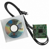
MA180021
Description
MODULE PLUG-IN 18F87J50 FS USB
Manufacturer
Microchip Technology
Series
PIC®r
Specifications of MA180021
Accessory Type
Plug-In Module (PIM) - PIC18F87J50
Silicon Manufacturer
Microchip
Core Architecture
PIC
Core Sub-architecture
PIC18
Features
Full Speed USB Demonstration, Operated Either Stand Alone Or As Plug-In Module
Silicon Core Number
PIC18F
Silicon Family Name
PIC18FxxJxx
Lead Free Status / RoHS Status
Lead free / RoHS Compliant
For Use With/related Products
HPC Explorer Board (DM183022) or PIC18 Explorer Board (DM183032)
For Use With
DM183032 - BOARD EXPLORER PICDEM PIC18DM183022 - BOARD DEMO PIC18FXX22 64/80TQFP
Lead Free Status / RoHS Status
Lead free / RoHS Compliant
Available stocks
Company
Part Number
Manufacturer
Quantity
Price
Company:

Part Number:
MA180021
Manufacturer:
Microchip Technology
Quantity:
135


3.4
© 2007 Microchip Technology Inc.
LINEAR REGULATOR/POWER MANAGEMENT
The USB interface provides +5V (nominal) at up to 500 mA (only 100 mA can be
ensured) for use by USB peripheral devices. In order to take advantage of this bus
provided power, a 3.3V low drop out, low quiescent current linear regulator
(TC1108-3.3VDB) has been included on the PIM. This enables the PIM to be purely bus
powered, providing power to both the PIM and the HPC Explorer board if connected.
Alternatively, when used in conjunction with the HPC Explorer, the PIM may obtain
power from the HPC board. When a suitable power source is connected to power jack,
J1 on the HPC Explorer board, the board will natively produce a regulated 5V provided
by the on-board adjustable linear regulator. When a PIM requiring 3.3V (such as the
PIC18F87J50 FS USB PIM) is plugged in, resistor, R2, located on the PIM alters the
feedback circuit of the adjustable linear regulator and configures it to produce 3.3V.
Therefore, no soldering or other modification is required to either the HPC Explorer or
the PIC18F87J50 FS USB PIM when they are used together.
Jumper, JP4, on the PIM serves two main purposes. JP4 is located in series with the
+5V V
exact electrical location). In this location, the jumper cap can be removed, and a digital
current meter can be inserted across the posts of the header. This can be quite useful
during development, as it offers a means of determining how much current the applica-
tion (both the PIM and the HPC Explorer board if connected) is actively consuming from
the USB port. This is especially important when developing bus powered USB
applications that are intended to be fully USB compliant.
All USB devices are supposed to implement a low-power USB Suspend mode. The
host PC may, at its own discretion, halt all USB traffic (including Start-of-Frame
packets) to your device for more than 3 ms. Upon detecting this condition, the USB
peripheral device should drop to a low-power suspend state, whereby it draws no more
than 500 μA (or in some cases, 2.5 mA; see the USB 2.0 specifications section 7.2.3)
from the +5V V
useful for detecting when the low-power suspend condition is supposed to begin and
when it ends. The TC1108-3.3VDB linear regulator was chosen for its low dropout, low
quiescent current consumption and good transient response capability.
BUS
Hardware Configuration/Jumper Settings
supply from the USB cable to the rest of the PIM board (see Figure A-1 for
BUS
supply. Two USB interrupts, UIR<IDLEIF> and UIR<ACTVIF>, are
DS51678A-page 13
Related parts for MA180021
Image
Part Number
Description
Manufacturer
Datasheet
Request
R

Part Number:
Description:
Manufacturer:
Microchip Technology Inc.
Datasheet:
Part Number:
Description:
Manufacturer:
Microchip Technology Inc.
Datasheet:
Part Number:
Description:
Manufacturer:
Microchip Technology Inc.
Datasheet:
Part Number:
Description:
Manufacturer:
Microchip Technology Inc.
Datasheet:
Part Number:
Description:
Manufacturer:
Microchip Technology Inc.
Datasheet:
Part Number:
Description:
Manufacturer:
Microchip Technology Inc.
Datasheet:
Part Number:
Description:
Manufacturer:
Microchip Technology Inc.
Datasheet:
Part Number:
Description:
Manufacturer:
Microchip Technology Inc.
Datasheet: