TLRBP TDK Corporation, TLRBP Datasheet - Page 22
TLRBP
Manufacturer Part Number
TLRBP
Description
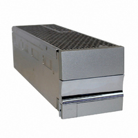
BLANKING PANEL
Manufacturer
TDK Corporation
Series
TLr
Specifications of TLRBP
Accessory Type
Blank Panel
For Use With
285-1646 - PWR SUP FNT END 48V 1000W 20A285-1645 - PWR SUP FNT END 24V 1000W 40A
Lead Free Status / RoHS Status
Lead free / RoHS Compliant
For Use With/related Products
TL Series
Lead Free Status / RoHS Status
Lead free / RoHS Compliant, Lead free / RoHS Compliant
Other names
285-1648


TLR5-S S ERIES POWER SYSTEM
5.4 Reference ground
The polarity on this rack is universal. Connect your reference ground to either the negative out-
put or positive output depending on the desired polarity. The connection is a double ¼" studs
with 5/8" centers.
5.5 Alarms and control
Access to alarms and control signals is accomplished via a rear mounted connector (p/n 43045-
2019, Molex) as shown in Figure 12. Table 12 provides a pin functional description.
Page. 22
Revision A3 : July 2005
· The pin out of the alarm connector on the rack is a 180° difference from a standard Molex
· AC fail, DC fail, and Thermal limit fail alarms are all open collector, opto-coupled, active
· Applying 5 V between pins 16 and 17 will shut all power modules down. Removing the 5V
connector. See Figure 11 & Figure 12.
high on failure/active low normally (software or factory configurable), and referenced to pin 17.
will cause the power module to power back up.
The pin is able to sink 10 mA of current at 5 V and 5 mA at TTL voltages.
Figure 12 - Alarm and signal connector
20
10
11
Figure 13 - Alarm cable pin out
1
10
20
11
1
Related parts for TLRBP
Image
Part Number
Description
Manufacturer
Datasheet
Request
R

Part Number:
Description:
TDK DC to DC Converters, DC to AC Inverters
Manufacturer:
TDK Corporation
Datasheet:
Part Number:
Description:
TDK DC to DC Converters, DC to AC Inverters
Manufacturer:
TDK Corporation
Datasheet: