S8T-BUS01 Omron, S8T-BUS01 Datasheet - Page 7
S8T-BUS01
Manufacturer Part Number
S8T-BUS01
Description
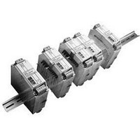
CONNECTOR AC/DC BUS LINE
Manufacturer
Omron
Series
S8TSr
Datasheet
1.S8TS-06024..pdf
(14 pages)
Specifications of S8T-BUS01
Accessory Type
Bus Line Connectors
Output 1 Vdc +
0VDC
Mounting Type
Din Rail
Product
Switching
Mounting Style
PCB
For Use With
S8TS Model Power Supplies
Lead Free Status / RoHS Status
Lead free / RoHS Compliant
For Use With/related Products
S8TS Power Supplies
Lead Free Status / Rohs Status
Lead free / RoHS Compliant
Other names
S8TBUS01


Mounting and Removing Bus Line
Connectors
Pay attention to the following points to maintain electrical
characteristics.
Do not insert/remove the Connectors more than 20 times.
Do not touch the Connector terminals.
To remove the Connectors, insert a flat-bladed screwdriver
alternately at both ends.
Wiring Linked Blocks
When linking Blocks together, wire input lines to one Basic Block
only, otherwise inputs may be shorted internally resulting in damage
to the Block.
Do not cross-wire Blocks or wire between a Block and another
device. If the current exceeds the rated current, Bus Line Connectors
may be damaged.
When Basic Blocks are linked together, it is necessary to wire the PE
terminal of only one Basic Block, not all the Blocks.
Series Operation and ± Output
Using 2 Basic Blocks enables series operation and the use of
± output. An external diode is not required for S8TS-06024@ and
S8TS-03012@ models, but is required for S8TS-02505@ models.
Use the following as a rough guide for selecting the diode.
Note: Series operation is possible with different specifications, but the
Type
Withstand voltage (V
Current with normal direction (I
current that flows to the load must not exceed the rated output
current of any Block.
Incorrect
Do not wire inputs to more than one
Incorrect
RRM
)
L
Do not use cross-wire Blocks.
N
L
F
) At least twice the rated output current
N
Schottky barrier diode
At least twice the rated output voltage
L
L
−V+V
N
N
L
N
Adjusting Output Voltage for Parallel
Operation
The Blocks are factory-set to the rated output voltage. When
adjusting output voltages, set the same values for Blocks with output
voltage adjuster (V.ADJ) before linking them together. Adjust the set
values within the limits given in the following table.
Do not adjust output voltages after Blocks are linked together. The
output voltage may become unstable.
Inrush Current
The inrush current per Basic Block is 25 A max. at 100 VAC and 50 A
max. at 200 VAC. When N Blocks are linked together, the inrush
current will be equal to N times that for 1 Basic Block. Be sure to use
a fuse with the appropriate fusing characteristics or a breaker with
the appropriate tripping characteristics.
Leakage Current
The leakage current per Basic Block is 0.35 mA max. at 100 VAC
and 0.7 mA max. at 240 VAC. When N Blocks are linked together,
the leakage current will be equal to N times that for 1 Basic Block.
Mounting
Mounting Direction
Use standard mounting only. Using any other mounting method will
prevent proper hear dissipation and may result in deterioration or
damage of internal parts.
24/12-V models
S8TS-03012@
S8TS-06024@
Standard mounting
Face-up mounting
Other mounting methods
L
N
Load
Model number
Series Operation
Standard mounting
Correct
S8T
-BUS02
5-V models
L
N
Load
0.12 V max.
0.24 V max.
Difference between output voltages
Yes
No
No
Face-up mounting
24/12-V models 5-V models
Incorrect
L
Load
N
Load
± Output
S8T
-BUS02
L
S8TS
Load
N
Load
7
Related parts for S8T-BUS01
Image
Part Number
Description
Manufacturer
Datasheet
Request
R

Part Number:
Description:
CONNECTOR AC BUS LINE
Manufacturer:
Omron
Datasheet:

Part Number:
Description:
CONNECTOR DC LINE BUS
Manufacturer:
Omron
Datasheet:
Part Number:
Description:
DC BACKUP BLOCK 24V 3.7/8A
Manufacturer:
Omron
Datasheet:
Part Number:
Description:
BUFFER BLOCK 22.5V 2.5A
Manufacturer:
Omron
Datasheet:

Part Number:
Description:
G6S-2GLow Signal Relay
Manufacturer:
Omron Corporation
Datasheet:
Part Number:
Description:
Compact, Low-cost, SSR Switching 5 to 20 A
Manufacturer:
Omron Corporation
Datasheet:
Part Number:
Description:
Manufacturer:
Omron Corporation
Datasheet:
Part Number:
Description:
Manufacturer:
Omron Corporation
Datasheet:
Part Number:
Description:
Manufacturer:
Omron Corporation
Datasheet:
Part Number:
Description:
Manufacturer:
Omron Corporation
Datasheet:
Part Number:
Description:
Manufacturer:
Omron Corporation
Datasheet: