S8T-BUS01 Omron, S8T-BUS01 Datasheet
S8T-BUS01
Specifications of S8T-BUS01


Related parts for S8T-BUS01


S8T-BUS01 Summary of contents
Page 1
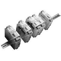
... Connector with DC line not connected (Not for parallel operation) Note: 1. One S8T-BUS01 Connector and one S8T-BUS02 Connector are included as accessories. 2. Bus Line Connectors are ordered separately. When connecting Power Supplies with Bus Line Connectors, order the Bus Line Connectors separately. ...
Page 2
... Specifications ■ Ratings/Characteristics 12/24-V Models (Basic Block: S8TS-06024@/S8TS-03012@) Item Efficiency (TYP.) Input Voltage (See note 1.) Frequency (See note 1.) Current 100 V input 200 V input Power factor Harmonic current emissions Leakage current 100 V input 240 V input Inrush current 100 V input (See note 5.) ...
Page 3
... Models (Basic Block: S8TS-02505@) Item Efficiency (typical) Input Voltage (See note 1.) Frequency (See note 1.) Current 100 V input 200 V input Power factor Harmonic current emissions Leakage current 100 V input 240 V input Inrush current 100 V input (See note 5.) 200 V input Output Voltage adjustment range ...
Page 4
... Connections ■ Block Diagrams S8TS-06024@ and S8TS-03012@ AC (L) Fuse Noise 2.0 A filter INPUT AC (N) Rectifier Connected to Bus Line Connector S8TS-02505@ AC(L) Fuse Noise 2.0 A filter INPUT AC(N) Rectifier Connected to Bus Line Connector Inrush Harmonic Smooth- Rectifier and current current ing smoothing ...
Page 5
... G Undervoltage Detection Output (DC LOW OUT): Open Collector output H DC Output Terminal (–V): Connect load lines to this terminal Output Terminal (+V): Connect load lines to this terminal. J Slider: Slide to the lock side when connecting. Unlock the slider when disconnecting. Connector with DC Line Connected S8T-BUS01 Bus Line Connector ...
Page 6
... Using Parallel Operation Use the S8T-BUS01 (DC line connected). (See Figure 1.) The S8T-BUS01 Bus Line Connector is equipped with a selector to prevent erroneous connection of Blocks with different output voltage specifications. Slide the selector to the output voltage for parallel operation. Note: Parallel operation is enabled by using a current balance function ...
Page 7
... Basic Block, not all the Blocks. Series Operation and ± Output Using 2 Basic Blocks enables series operation and the use of ± output. An external diode is not required for S8TS-06024@ and S8TS-03012@ models, but is required for S8TS-02505@ models. Use the following as a rough guide for selecting the diode. ...
Page 8
... Models Rated output voltage The values shown in the above diagrams are for reference only. Note: Do not turn ON the input power again until the cause of the overvoltage has been removed. S8TS N+1 Redundant System 0 −20 − Ambient temperature (°C) Overvoltage ...
Page 9
... ON residual voltage max. OFF leakage current: 0.1 mA max. 3. The indicators become dimmer as the output voltage approaches 0 V. Undervoltage Detection Output Blocks with Screw Terminals DC LOW OUT −V S8TS Voltage status Output status (See note 2.) Approx. 80% ON min. of the rated output voltage Approx ...
Page 10
... Eight, M4 pan-head 1 screw 35.5 35.5 50 1.8 11.5 1 spring washer 4.8 S8TS LOCK 4 35 120 LOCK 4 35 120 7.3± 0.15 35± 27± 0.3 0.15 15(5)* 1 *Values in parentheses are for the PFP-50N. 16 35± 1.5 10 ...
Page 11
... S8TS. Just link Basic Blocks for redundant operation in parallel to enable N+1 redundant operation. A current balance function is used for S8TS N+1 redundant operation so that each Block provides the same current. If one Power Supply fails, the remaining Power Supplies share the load of the failed Power Supply, and operation continues with each Power Supply providing more current ...
Page 12
... Be sure to remove the sheet covering the Power Supply for machining before turning ON the power so that it does not interfere with heat dissipation. Use the following material for the wires to be connected to the S8TS to prevent smoking or ignition caused by abnormal loads. Recommended Wire Size for Single-unit ...
Page 13
... Buzzing Noise When the Input Is Turned ON A harmonic current suppression circuit is built into the input power. This circuit can create noise when the input is turned ON, but it will last only until the internal operation stabilizes and does not indicate any problem in the Power Supply. S8TS 13 ...
Page 14
... Please read and understand this catalog before purchasing the products. Please consult your OMRON representative if you have any questions or comments. WARRANTY OMRON's exclusive warranty is that the products are free from defects in materials and workmanship for a period of one year (or other period if specified) from date of sale by OMRON. OMRON MAKES NO WARRANTY OR REPRESENTATION, EXPRESS OR IMPLIED, REGARDING NON-INFRINGEMENT, MERCHANTABILITY, OR FITNESS FOR PARTICULAR PURPOSE OF THE PRODUCTS ...