TLR5 TDK Corporation, TLR5 Datasheet
TLR5
Specifications of TLR5
Available stocks


Related parts for TLR5

TLR5 Summary of contents
Page 1
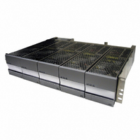
... TLR5 - COMPACT DC POWER SYSTEM Installation, Operation, and Maintenance Manual TLR5 July 2005 Version A3 ...
Page 2
... Reference ground 5.4 Alarms and control 5.5 6) Test and Turn Power up 6.1 7) Troubleshooting Problems and Solutions 7.1 Short circuit & Current Limit 7.2 8) Installationsanleitung (German Installation) 3055 Del Sol Blvd • San Diego, CA 92154 • 1-800-LAMBDA-4 TLR5-S S ERIES POWER SYSTEM ...
Page 3
... CAUTION: ALL POWER MODULES EMPLOY INTERNAL DOUBLE POLE/NEUTRAL FUSING 3055 Del Sol Blvd • San Diego, CA 92154 • 1-800-LAMBDA-4 TLR5-S S ERIES POWER SYSTEM WARNING: HIGH LEAKAGE CURRENT: EARTH CONNECTION ESSENTIAL BEFORE CONNECTING SUPPLY Use double hole, UL listed lugs for all DC connections to prevent lug rotation and inad- vertent contact with other circuits ...
Page 4
... TLR5-S S ERIES POWER SYSTEM 1.2 FCC Compliance Statement 1.2.1 Note This device complies with Part 15 of FCC Rules. Operation is subject to the following two condi- tions: 1. This device may not cause harmful interference, and 2. This device must accept any interference received, including interference that may cause undesired operation ...
Page 5
... TL100024 TL150024 Heat Dissipation 48V Power Modules Model Typical BTU/hr TL50048 TL100048 TL150048 TL200048 TL250048 3055 Del Sol Blvd • San Diego, CA 92154 • 1-800-LAMBDA-4 TLR5-S S ERIES POWER SYSTEM Max BTU/hr 413 490 619 718 Table 1 Max BTU/hr 247 308 493 ...
Page 6
... TLR5-S S ERIES POWER SYSTEM 2.2 AC Requirements 2.2.1 AC input circuit breaker sizing Table 4 shows the required input voltages for the available power modules. The power modules under wide line (WL) can be connected to a nominal input voltage between 100 V & 240V. The power modules under high line (HL) can be connected to a nominal input voltage between 200 V & ...
Page 7
... Table 5, Table 6, or Table 7, to the rear terminal block seen in Figure 7. The tables are separated by system voltage, i.e. 12 volt, 24 volt volt systems. 3055 Del Sol Blvd • San Diego, CA 92154 • 1-800-LAMBDA-4 TLR5-S S ERIES POWER SYSTEM N+1 DC Out Page. 7 ...
Page 8
... TLR5-S S ERIES POWER SYSTEM 2.2.2.2 Dual feed AC Line 1 AC Line 2 Figure 2 - Dual Feed AC Wiring Architecture A dual feed architecture powers three power modules on AC feed 1 and two power module on AC feed 2. Connect the AC source that is sized according to Table 5, Table 6, or Table 7, to the rear terminal block seen in Figure 8 ...
Page 9
... The tables below use the absolute minimum input voltage at which the power modules will run at to determine AC requirements corresponds to low line and 180 V corresponds to high line. 3055 Del Sol Blvd • San Diego, CA 92154 • 1-800-LAMBDA-4 TLR5-S S ERIES POWER SYSTEM N+1 DC Out Page. 9 ...
Page 10
... TLR5-S S ERIES POWER SYSTEM Recommended AC Circuit Breaker & Wire Sizes (12V system) Number of Power Minimum Model Number Modules on Input of Power AC Feed Voltage Module 90 TL50012 180 TL50012 1 90 TL75012 180 TL75012 90 TL50012 180 TL50012 2 90 TL75012 180 TL75012 90 TL50012 180 TL50012 3 90 ...
Page 11
... TL150024 90 TL50024 180 TL50024 5 90 TL100024 180 TL100024 180 TL150024 3055 Del Sol Blvd • San Diego, CA 92154 • 1-800-LAMBDA-4 TLR5-S S ERIES POWER SYSTEM Maximum Circuit Breaker 90°C Minimum Wire rated AC Minimum Value Gauge to use at 30°C Current (Amps) to use (Amps ...
Page 12
... TLR5-S S ERIES POWER SYSTEM Recommended AC Circuit Breaker & Wire Sizes (48V system) Number of Power Minimum Model Number Modules on Input of Power AC Feed Voltage Module 90 TL50048 180 TL50048 90 TL100048 1 180 TL100048 180 TL150048 180 TL200048 180 TL250048 90 TL50048 180 TL50048 90 TL100048 2 180 TL100048 ...
Page 13
... TLR5-S S ERIES POWER SYSTEM Desciption SH Ring Terminal 1/4 Stud SH Ring Terminal 8 Stud SH Ring Terminal 1/4 Stud SH Ring Terminal 8 Stud SH Ring Terminal 1/4 Stud SH Ring Terminal 8 Stud SH Lug Long Barrel 8 Stud SH Lug Standard Barrel 1/4 Stud Table 8 Page ...
Page 14
... TLR5-S S ERIES POWER SYSTEM 2.3.1 DC circuit 1 Figure Wiring Diagram (Circuit #1) Each system is equipped with two double hole lug DC connection pads located behind the rear panel as shown in Figure 10. Select a wire size for each position according to the maximum load current as shown in Table 9. If the rack is to receive additional power modules at a later date, select wiring for the maximum future installation ...
Page 15
... TLR5-S S ERIES POWER SYSTEM Table 9 Desciption SH Ring Terminal 1/4 Stud SH Ring Terminal 1/4 Stud SH Ring Terminal 1/4 Stud SH Ring Terminal 1/4 Stud SH Lug Standard Barrel 1/4 Stud DH Lug Standard Barrel 1/4 Stud, 5/8 Center ...
Page 16
... TLR5-S S ERIES POWER SYSTEM 2.4 Torque settings Table 11 shows the recommended torque settings for all mechanical and electrical connections according to screw or nut size. Not all screw sizes may be present on a particular rack. Recommended Torque Settings Screw or Nut Size 4-40 6-32 8-32 ...
Page 17
... Lambda recommends that you use at least two screws per bracket. 3055 Del Sol Blvd • San Diego, CA 92154 • 1-800-LAMBDA-4 TLR5-S S ERIES POWER SYSTEM Mounting Brackets Figure 5 - Front View Page ...
Page 18
... TLR5-S S ERIES POWER SYSTEM 5.2 AC input Knockouts are provided to route AC cables to the proper connections on the single and dual feed shelves. Remove the cutout and place the provided cord grip in the knockout to provide protec- tion and security to the AC cord. 5.2.1 Single Feed For 110 Vac service, connect your line/hot to Line 1, labeled on the AC terminal block shown in Figure 7 ...
Page 19
... Line 2/N2. These connections are made with ring terminals on a #8-32 screws, and torque according to Table 11. Connect both grounds to the ¼" studs labeled "ground", and torque according to Table 11. 3055 Del Sol Blvd • San Diego, CA 92154 • 1-800-LAMBDA-4 TLR5-S S ERIES POWER SYSTEM Line 1/N1 Line 1 2-1 1 ” Knockouts Page ...
Page 20
... When ready to power up, plug in the AC cord into the proper receptacle or turn on the AC breaker. 5.2.3 Individual Feed The TLR5 comes with two different types of Individual AC feeds. The first type contains five IEC320/C13 plugs rated for 15 amps max a piece. The second type contains five IEC320/C19 plugs rated for 20 amps max a piece For any AC service between 100 Vac to 240 Vac, connect each line cord into the appropriate AC receptacle on the rear on the rack as seen in Figure 9 ...
Page 21
... Figure Connections Route DC cables out the side of the rack through the cable routing holes seen in Figure 11. Figure 11 - Cable routing holes 3055 Del Sol Blvd • San Diego, CA 92154 • 1-800-LAMBDA-4 TLR5-S S ERIES POWER SYSTEM Cable routing holes Page. 21 Revision A3 : July 2005 ...
Page 22
... TLR5-S S ERIES POWER SYSTEM 5.4 Reference ground The polarity on this rack is universal. Connect your reference ground to either the negative out- put or positive output depending on the desired polarity. The connection is a double ¼" studs with 5/8" centers. 5.5 Alarms and control Access to alarms and control signals is accomplished via a rear mounted connector (p/n 43045- 2019, Molex) as shown in Figure 12 ...
Page 23
... OR/WHT Module 0 (leftmost slot) DC Fail. 4 OR/BLK Module 1 DC Fail 3 OR Module 2 DC Fail 2 WHT Module 3 DC Fail 1 YLW Module 4 (rightmost slot) DC Fail 3055 Del Sol Blvd • San Diego, CA 92154 • 1-800-LAMBDA-4 TLR5-S S ERIES POWER SYSTEM Table 12 Page. 23 Revision A3 : July 2005 ...
Page 24
... TLR5-S S ERIES POWER SYSTEM 6 Test and Turn 6.1 Power up Once all AC and DC connections have been secured and checked, install each power module sequentially by sliding and latching each power module into a rack position as shown in Figure 14. The power module latches must be open for installation. Attempting to install the power modules with the latches closed will result in mechanical damage to the power modules and the rack ...
Page 25
... Module AC fail 0-4 on alarm cable ALM LED Illuminated Thermal Limit Failure 3055 Del Sol Blvd • San Diego, CA 92154 • 1-800-LAMBDA-4 TLR5-S S ERIES POWER SYSTEM Solutions Replace bad power module unit - unlatch, remove and replace with spare System short circuit - inspect and replace ...
Page 26
... TLR5-S S ERIES POWER SYSTEM 7.2 Short circuit & Current Limit I can be adjusted up to +105% of the rated current of the power module. The system voltage will Limit remain constant which point the system voltage will drop quickly toward 0 VDC , as in Figure Limit 15. Once a 24V or 48V power module drops below 12 VDC for more than 5 seconds, the system will shut down ...
Page 27
... Beim Aufstellen des Gerätes ist daraf zu achten das alle Anforderungen gemäß EN60950 eingehalten werden. Installation must comply with EN60950. 3055 Del Sol Blvd • San Diego, CA 92154 • 1-800-LAMBDA-4 TLR5-S S ERIES POWER SYSTEM Netzteile fuer (200V - 240) TL150048 ...