FNP1500-48G POWER ONE, FNP1500-48G Datasheet - Page 7
FNP1500-48G
Manufacturer Part Number
FNP1500-48G
Description
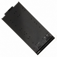
PWR SUP 1512W 48V FRONT END
Manufacturer
POWER ONE
Series
FNP1500r
Type
Commercial, Industrialr
Specifications of FNP1500-48G
Voltage - Output
12V, 48V
Number Of Outputs
2
Power (watts)
1500W
Applications
Commercial
Power Supply Type
Switching (Closed Frame)
Voltage - Input
85 ~ 264VAC
Mounting Type
Chassis Mount
1st Output
48 VDC @ 32.2A
2nd Output
12 VDC @ 1A
Size / Dimension
11" L x 1.6" W x 5.6" H (279.4mm x 40.5mm x 141.2mm)
Power (watts) - Rated
1512W
Operating Temperature
0°C ~ 50°C
Efficiency
90%
Approvals
CE, cUL, EN, TUV, UL
Output Voltage
48/12V
Output Power (max)
1512W
Input Frequency
47 to 63Hz
Screening Level
Commercial
Product Length (mm)
279.4mm
Operating Temperature Min Deg. C
0C
Operating Temperature Max Deg. C
70C
Mounting Style
Desktop
Product
Switching
Commercial/medical
Commercial
Output Power Rating
1548 W
Input Voltage
85 VAC to 264 VAC
Output Voltage (channel 1)
48 V
Output Current (channel 1)
32.2 A
Output Voltage (channel 2)
12 V
Output Current (channel 2)
1 A
Dimensions
11 in L x 5.6 in W x 1.6 in H
Brand/series
FNP1500 Series
Configuration
Enclosed
Operation
Linear
Output
12 VDC @ 1 A, 12 VDC @ 1 A, 48 VDC @ 25.4 A, 48 VDC @ 32.2 A
Power, Output
1512, 1212 W
Primary Type
AC-DC
Special Features
PFC
Voltage, Input
230 VAC
Voltage, Output
12, 12, 48, 48 VDC
Lead Free Status / RoHS Status
Lead free / RoHS Compliant
3rd Output
-
4th Output
-
Lead Free Status / Rohs Status
Compliant
Other names
179-2396


Output Connector Pinning and Signal Specification
MCD10074 Rev. 1.2, 15-Apr-10
Overtemperature /
Fan Fail
AC Fail /
Power down warning
Power Supply Present
DC Fail /
Output voltage fault
Internal ground
ADDR0, I
bus
ADDR1, I
bus
ADDR2, I
bus
ADDR3, I
bus
ADDR4, I
bus
DATA, I
CLOCK, I
V
V
Logic ground
Output inhibit
V sense +
V sense -
12V models
Output margin
48V models
12V models
Synch. startup
48V models
V
12V models
V
12V models
V
48V models
V
48V models
o2
o2
o1
o1
o1
o1
Output Connector
+ output
– output
+ output
– output
+ output
– output
Description
2
C data line
2
2
2
2
2
2
C address
C address
C address
C address
C address
C clock line
P2, P4, P6, P8,
P7, P9, P11
P1, P3, P5,
P1, P3, P5
P2, P4, P6
Location
P10, P12
Pin
U3
U5
R1
R2
R3
U1
U2
U4
T1
T2
T3
T4
T5
S1
S2
S3
S4
S5
R4
R4
R5
R5
PS active when pulled low (DC-DC stage off when left
open) Referenced to logic GND
Internally connected over 10 Ω to Auxiliary GND. Wire
OC-output, protected by 16 V Zener diode and a 10 Ω
OC-output, protected by 16 V Zener diode and a 10 Ω
OC-output, protected by 16 V Zener diode and a 10 Ω
separately form Auxiliary - and main output GND to
Open or connected over resistor to internal ground.
Internal ground (V
Auxiliary ground pin, insulated from main output
Auxiliary power pin, insulated from main output
Open or connected to synch startup circuit,
Open or connected to synch startup circuit,
resistor in series, referenced to logic GND
resistor in series, referenced to logic GND
resistor in series, referenced to logic GND
referenced to V
referenced to V
(Internally connected to V
(Internally connected to V
Resistor (1 kΩ) connected to logic GND
Do not connect the internal grounds in
Open or connected to V
Open or connected to internal ground
Open or connected to V
DIP switch or wire to internal ground,
DIP switch or wire to internal ground,
DIP switch or wire to internal ground,
DIP switch or wire to internal ground,
DIP switch or wire to internal ground,
minimize noise on signals and I
Do not connect the margin pins in
Do not connect the margin pins in
Internally pull up to 5V (10 kΩ).
Internally pull up to 5V (10 kΩ).
Internally pull up to 5V (10 kΩ).
Internally pull up to 5V (10 kΩ).
Internally pull up to 5V (10 kΩ).
(+8 % V
systems with several units.
systems with several units.
systems with several units.
referenced to logic GND
referenced to logic GND
Leave open if not used.
Page 7 of 17
I
I
2
2
C compatible signal
C compatible signal
Main output + pins
Main output – pins
Main output + pins
Main output – pins
o1
o1
) or V
o1
o1
– line before the output filter).
- at the output connector
- at the output connector
Type
sense+
o1
o1
o1
o1
(-8 % V
& FNR-3 Power Shelf Data Sheet
+ at the load
+ over 100 Ω)
- at the load
- over 100 Ω)
o1
2
)
C.
FNP1500/1800 Front-Ends
< 0.4 V @ 20 mA
< 0.4 V @ 20 mA
< 0.4 V @ 20 mA
5 V or 3.3 V logic
5 V or 3.3 V logic
Switch closed
Switch closed
Switch closed
Switch closed
Switch closed
Switch open
Switch open
Switch open
Switch open
Switch open
Low level
High level
< 0.8 V
> 2.0 V
Pull up
Pull up
Pull up
Pull up
Open
www.power-one.com
dU < 3 V
dU < 3 V
60 VDC
3.5 mA
V max
3 VDC
20 mA
20 mA
10 mA
20 mA
30 mA
30 mA
I max
15 V
15 V
10 V
15 V
10 V
3mA
2mA
12V
12V
5V
5V
5V
5V
5V
pp
pp
Related parts for FNP1500-48G
Image
Part Number
Description
Manufacturer
Datasheet
Request
R

Part Number:
Description:
PWR SUP 1512W 12V FRONT END
Manufacturer:
POWER ONE
Datasheet:

Part Number:
Description:
SWITCHING POWER SUPPLIES, SINGLE OUTPUT, 80 WATTS
Manufacturer:
POWER ONE
Datasheet:
Part Number:
Description:
HAS SERIES - 30 WATT
Manufacturer:
POWER ONE
Datasheet:
Part Number:
Description:
SINGLE OUTPUT
Manufacturer:
POWER ONE
Datasheet:

Part Number:
Description:
BRS DC/DC converters(1.5 WATT)
Manufacturer:
Power-One
Datasheet:
Part Number:
Description:
3...15 Watt DC-DC Converter
Manufacturer:
Power-One
Datasheet:
Part Number:
Description:
HBS SERIES - 100 WATT
Manufacturer:
Power-One
Datasheet:
Part Number:
Description:
3...15 Watt DC-DC Converter
Manufacturer:
Power-One
Datasheet:
Part Number:
Description:
BUS DC/DC converters(3 WATT)
Manufacturer:
Power-One
Datasheet:
Part Number:
Description:
HES SERIES 150 WATT
Manufacturer:
Power-One
Datasheet:
Part Number:
Description:
1.25 WATT
Manufacturer:
Power-One
Datasheet: