ZUP120-1.8/U TDK Corporation, ZUP120-1.8/U Datasheet - Page 21
ZUP120-1.8/U
Manufacturer Part Number
ZUP120-1.8/U
Description
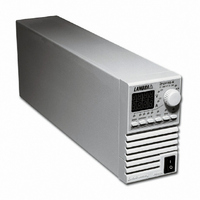
PWR SUP BENCH PROG 0-120V 216W
Manufacturer
TDK Corporation
Series
ZUPr
Type
Programmabler
Specifications of ZUP120-1.8/U
Load Regulation
0.01%
Voltage - Output
0 ~ 120V
Number Of Outputs
1
Power (watts)
216W
Applications
Commercial
Power Supply Type
Switching (Closed Frame)
Voltage - Input
85 ~ 265VAC
Mounting Type
Chassis Mount
1st Output
0 ~ 120 VDC @ 1.8A
Size / Dimension
13.78" L x 4.88" W x 2.76" H (350mm x 124mm x 70mm)
Power (watts) - Rated
216W
Operating Temperature
0°C ~ 50°C
Efficiency
82%
Approvals
CE, EN, UL
Line Regulation
0.01%
Power Supply Output Type
Variable
No. Of Outputs
1
Output Voltage
120V
Output Current
1.8A
Power Rating
216W
Input Voltage
85V AC To 265V AC
Length
350mm
Width
70mm
Accuracy
0.02% + 70 mV
Brand/series
ZUP
Current, Output
1.8 A
Display Type
Digital Meter
Power, Output
216 W
Power, Rating
216 W (Max.)
Regulation, Line
0.01% + 2 mA⁄1 mV + 0.005%
Regulation, Load
0.01% + 5 mA⁄2 mV + 0.005%
Standards
UL Listed, CE Marked
Temperature Coefficient
30 ppm⁄°C (CV)⁄100 ppm⁄°C (CC)
Temperature, Operating, Maximum
50 °C
Temperature, Operating, Minimum
0 °C
Voltage, Input
85-265 VAC
Voltage, Noise
80 mV @ 20 MHz BW
Voltage, Output
120 VDC
Voltage, Ripple
30 mV @ 5 Hz to 1 MHz
Lead Free Status / RoHS Status
Lead free / RoHS Compliant
3rd Output
-
2nd Output
-
4th Output
-
Lead Free Status / Rohs Status
RoHS Compliant part
Other names
285-1671
ZUP1201.8/U
ZUP1201.8/U


COM
VCVP
VCCP
RCCP
3.7.4 Single load connection, Remote Sensing
Fig. 3-3: Multiple load connections with distribution terminal
Remote Sensing is used in cases where, in Constant Voltage mode the load regulation is important at
the load terminals. Use twisted or shielded wires to minimize noise pick-up. If shielded wires are used,
the shield should be connected to the ground at one point, either the power supply chassis or the load
ground. The optimal point for the shield ground should be determined by experimentation. At Remote
Sensing, the maximum voltage drop allowed at the load wires is 0.5V per wire for 6V to 60V models and
2V per wire for 80V and 120V models.
COM
VCVP
VCCP
RCCP
3.7.5 Multiple load connections, radial distribution method
In cases of multiple loads connected to one supply, each load should be connected to the power
supply’s output terminals using separate pairs of wires. It is recommended that each pair of wires will be
as short as possible and twisted or shielded to minimize noise pick-up and radiation. The sense wires
should be connected to the power supply output terminals or to the load with the most critical load
regulation requirement.
- S
+S
Fig. 3-2: Remote Sensing, single load.
- S
+S
P
P
EXTERNAL CONTROL
EXTERNAL CONTROL
(ZUP rear panel view)
(ZUP rear panel view)
CONNECTOR
CONNECTOR
2
2
1
1
On/Off
Output Good
VRFV
VRFI
RCVP
On/Off
Output Good
VRFV
VRFI
RCVP
- LS
+LS
- LS
+LS
To Load Terminals
SUPPLY
POWER
SUPPLY
POWER
- LS
+LS
- V
- S
+S
+V
+ V
+ S
- V
- S
Shield
+
_
+
+
+
_
_
_
LOAD #1
LOAD #2
LOAD #3
LOAD
Related parts for ZUP120-1.8/U
Image
Part Number
Description
Manufacturer
Datasheet
Request
R

Part Number:
Description:
PWR SUP BENCH PROG 0-120V 432W
Manufacturer:
TDK Corporation
Datasheet:

Part Number:
Description:
ZERO UP PROGRAMMABLE POWER SUPPLIES
Manufacturer:
TDK Corporation
Part Number:
Description:
TDK DC to DC Converters, DC to AC Inverters
Manufacturer:
TDK Corporation
Datasheet:
Part Number:
Description:
TDK DC to DC Converters, DC to AC Inverters
Manufacturer:
TDK Corporation
Datasheet: