SWS1000L-48 TDK Corporation, SWS1000L-48 Datasheet - Page 17
SWS1000L-48
Manufacturer Part Number
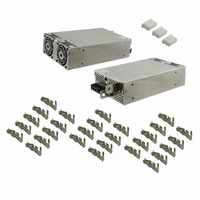
SWS1000L-48
Description
PWR SUP MED 48V 22A SGL OUTPUT
Manufacturer
TDK Corporation
Series
SWS1000Lr
Type
Commercialr
Specifications of SWS1000L-48
Power Supply Type
Switching (Closed Frame)
Voltage - Output
48V
Number Of Outputs
1
Power (watts)
1000W
Applications
Medical
Voltage - Input
85 ~ 265VAC
Mounting Type
Chassis Mount
1st Output
48 VDC @ 22A
Size / Dimension
9.45" L x 5.91" W x 2.4" H (240mm x 150mm x 61mm)
Power (watts) - Rated
1056W
Operating Temperature
-20°C ~ 74°C
Efficiency
86%
Approvals
CSA, DENAN, EN, IEC, UL
Power Supply Output Type
Fixed
No. Of Outputs
1
Output Voltage
48V
Output Current
22A
Power Rating
1056W
Input Voltage
85V AC To 265V AC / 120V DC To 350V DC
Brand/series
SWS Series
Configuration
Enclosed
Output
48 VDC @ 22 A
Power, Output
1056 W
Primary Type
AC-DC
Special Features
Parallelable, PFC, Remote On/Off, Remote Sense
Voltage, Input
85 to 265/120 to 350 VAC/VDC
Voltage, Output
48 VDC
Lead Free Status / RoHS Status
Lead free / RoHS Compliant
3rd Output
-
2nd Output
-
4th Output
-
Lead Free Status / Rohs Status
RoHS Compliant part
Other names
285-1798
SWS1000L48
SWS1000L48
Available stocks
Company
Part Number
Manufacturer
Quantity
Price

Part Number:
SWS1000L-48
Quantity:
129


・All specifications are subject to change without notice.
SWS
[The PHD connector manufacture method]
This product is using SPHD-001T-P0.5 or SPHD-002T-0.5 connec-
tor made from JAPAN SOLDERLESS TERMINAL MFG CO LTD.
Regarding to manufacture of a connector, it becomes the
regulation as following.
a). Appricable Wire and Crimping tool
Wire size is AWG#26 - AWG#22 and insulation outer dia is
- φ1.5 mm.
Appreciable wire per barrel size is UL1007 (standard wire)
and its equivalent standard wire can be used. Regarding the
AWG#22, use UL1061 or its equivalent standard wire, because
wire insulation outer diameter of UL1061 is small.
Crimping tool is as below.
b). Crimping Operation
The reference value of wire strip is 2.3mm. As wire strip length dif-
fers depending on type of wire and crimping method, decide the
best wire strip length considering processing condition. When
wire is stripped, do not damage or cut off wire conductors.
Table of crimp height
SPHD-001T-P0.5
SPHD-002T-P0.5
Note1. Crimp height at wire barrel should be set to pre-determined
Note2. Adjust crimp height at wire insulation barrel to the extent
Note3. Crimping condition at wire insulation barrel is as below Fig.1.
Note4. For AWG#28, #26, #24, use UL1007 type. For AWG#22,
AP-K2 or AP-KS MKS-LS-10 or MKS-L-10 SPHD-001-05/SPHD-002-05
(1) The output load line and input line shall be separated to
(2) The sensing lines shall be twisted and separated from the
(3) Use all lines as thick and short as possible to make lower
(4) Attaching a capacitor to the load terminals can eliminate noise.
(5) For safety and EMI considerations, connect terminal to the
(6) Recommended torque for the terminal :
UL1007
UL1007
UL1061
UL1007
UL1007
UL1007
Crimping tool
Type
Type
SWS600L Input terminal (M4 screw)
SWS1000L Input terminal (M4 screw)
improve noise sensitivity.
output lines for remote sensing.
impedance, clamping core at both input and output wires
benefi t EMI performance.
mounting set ground terminal, power supply and load mount-
ing on aluminum plate is recommended for EMI setting.
dimensions.
that wire insulation is slightly pressed, and set it so that
crimping is not excessivery.
use UL1061 type.
Wire
Wire
AWG #26
AWG #24
AWG #22
AWG #28
AWG #26
AWG #24
600L, 1000L
Size
Size
Output terminal (M5 screw)
Output terminal (M8 bolt & nut) : 10.8 N · m (110kgf · cm)
Crimping applicator
Insulation O.D
Insulation O.D
(mm)
(mm)
1.3
1.5
1.4
1.2
1.3
1.5
(M4 screw)
Conductor part Insulation part
Conductor part Insulation part
0.60 - 0.70
0.65 - 0.75
0.70 - 0.80
0.55 - 0.60
0.60 - 0.65
0.62 - 0.67
: 1.27 N · m (13.0kgf · cm)
: 2.5 N · m (25.5kgf · cm)
: 1.27 N · m (13.0kgf · cm)
: 1.27 N · m (13.0kgf · cm)
Crimp height (mm)
Crimp height (mm)
Dies
6. Wiring Method
1.8
1.8
1.7
1.6
1.7
1.8
φ
1.0
Check of crimping appearance visually for correct crimping as
referring to above Fig.2. Check the tensile strength at crimped
part when operation fi nishes.
Table of tensile strength at crimped part.
SPHD-001T-P0.5
SPHD-002T-P0.5
c). Inserting contact into housing
Inserting crimped contact into housing
Defect example of slation insertion
d). Mating and Unmating Connector
e). Routing of Wire
Routing wire so as not to apply external force to connector ex-
cept force to such an extent that wire slightly buckles, consider-
ing an enough length to route and fi xing of wire.
(2) Insert contact into housing without stopping to innermost.
(3) Check secure locking per each insertion by pulling wire softly
(1) Do not apply any pulling force to crimped part, and insert
(1) Inserting connector
(2) Unmating connector
UL1007 AWG#26
UL1007 AWG#24
UL1007 AWG#22
UL1007 AWG#28
UL1007 AWG#26
UL1007 AWG#24
Hold receptacle housing securely and insert into header
Hold all wires securely and fi x receptacle housing by fi n-
contact parallel to housing.
in order to check that contact does not come off housing. Be-
sides, check whether there is the backlash in the direction of
insertion axis.
straight against to header post until click sounds.
gers so as to pry, and then, withdraw it on the mating axis.
Wire conductor protruding
length is long.
Wire barrel bites wire
insulation.
Cover of contacting part
Wire size
Wire size
Contact
Fig.2: Examples of defective crimping
Fix receptacle housing Hold all wires
Requirement N min.
Requirement N min.
Insert with slanting
Wire conductor protruding
length is short.
Wire insulation is not
crimped sufficintry.
Header
Fig.1
20
30
40
15
20
30
Cover of contacting part
Housing
Actual value N
Actual value N
68.6 - 74.5
39.2 - 45.1
92.1 - 96.0
27.0 - 34.3
44.1 - 48.0
66.6 - 71.5
Wire conductor
comes off.
17
Related parts for SWS1000L-48
Image
Part Number
Description
Manufacturer
Datasheet
Request
R

Part Number:
Description:
POWER SUPPLY, SWITCH MODE, 12V
Manufacturer:
TDK Corporation
Datasheet:
Part Number:
Description:
POWER SUPPLY, SWITCH MODE, 15V
Manufacturer:
TDK Corporation
Datasheet:
Part Number:
Description:
POWER SUPPLY, SWITCH MODE, 24V
Manufacturer:
TDK Corporation
Datasheet:
Part Number:
Description:
POWER SUPPLY, SWITCH MODE, 5V
Manufacturer:
TDK Corporation
Datasheet:
Part Number:
Description:
POWER SUPPLY, SWITCH MODE, 3.3V
Manufacturer:
TDK Corporation
Datasheet:


Part Number:
Description:
TDK DC to DC Converters, DC to AC Inverters
Manufacturer:
TDK Corporation
Datasheet:
Part Number:
Description:
TDK DC to DC Converters, DC to AC Inverters
Manufacturer:
TDK Corporation
Datasheet: