SWS1000L-48 TDK Corporation, SWS1000L-48 Datasheet - Page 13
SWS1000L-48
Manufacturer Part Number
SWS1000L-48
Description
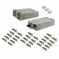
PWR SUP MED 48V 22A SGL OUTPUT
Manufacturer
TDK Corporation
Series
SWS1000Lr
Type
Commercialr
Specifications of SWS1000L-48
Power Supply Type
Switching (Closed Frame)
Voltage - Output
48V
Number Of Outputs
1
Power (watts)
1000W
Applications
Medical
Voltage - Input
85 ~ 265VAC
Mounting Type
Chassis Mount
1st Output
48 VDC @ 22A
Size / Dimension
9.45" L x 5.91" W x 2.4" H (240mm x 150mm x 61mm)
Power (watts) - Rated
1056W
Operating Temperature
-20°C ~ 74°C
Efficiency
86%
Approvals
CSA, DENAN, EN, IEC, UL
Power Supply Output Type
Fixed
No. Of Outputs
1
Output Voltage
48V
Output Current
22A
Power Rating
1056W
Input Voltage
85V AC To 265V AC / 120V DC To 350V DC
Brand/series
SWS Series
Configuration
Enclosed
Output
48 VDC @ 22 A
Power, Output
1056 W
Primary Type
AC-DC
Special Features
Parallelable, PFC, Remote On/Off, Remote Sense
Voltage, Input
85 to 265/120 to 350 VAC/VDC
Voltage, Output
48 VDC
Lead Free Status / RoHS Status
Lead free / RoHS Compliant
3rd Output
-
2nd Output
-
4th Output
-
Lead Free Status / Rohs Status
RoHS Compliant part
Other names
285-1798
SWS1000L48
SWS1000L48
Available stocks
Company
Part Number
Manufacturer
Quantity
Price

Part Number:
SWS1000L-48
Quantity:
129


・All specifications are subject to change without notice.
SWS
(a)
Example V1:5V R1:620Ω)
(b)
(c)
The standard specifi cation for maximum ripple value is mea-
sured by measurement circuit as below. When load lines are
longer, ripple becomes larger. In this case, electrolytic capaci-
tor, fi lm capacitor, etc. might be necessary to use across the
load terminal. The output ripple cannot be measured accurately
if the probe ground lead of oscilloscope is too long.
Fig.2.3 Examples of connecting remote ON/OFF circuit
Output Ripple & Noise
Power
Supply
12V
typ
600L, 1000L
12V
typ
12V
+
typ
-
150mm
47µ
2.2KΩ
150Ω
2.2KΩ
150Ω
2.2KΩ
150Ω
0.1µ
Coaxial Cable
1.5m
Load
AUX
CNT1
CNT2
TOG
G2
TOG
AUX
CNT1
CNT2
G2
AUX
CNT1
TOG
G2
CNT2
R1
Oscilloscope
20MHz
V1
SW
SW
SW
For series operation, both method (A) and (B) are possible.
There might be a step in the output rise waveform during series
operation.
Method (A)
Method (B)
Current balancing function is provided. Both operations mode
(A) and (B) are possible.
(A) To Increase the Output Current
Correct PC to PC terminal and COM to COM terminal, the current
balancing function activates and output current of each power
supply is equivalently supplied to load. Wires to PC terminals,
COM terminals shall be as short as possible and same length
and twisted.
(B) To Use as a Backup Power Supply
(1) Adjust the output voltage of each power supply to be same
(2) Use same length and type of wires for all load lines.
(3) Please make sure that the sum of output current values
(4) Parallel operation is possible up to 5 units.
(1) Adjust the output voltage (Vo) of each power supply to be
(2) Set power supply output voltage higher to compensate the
(3) Use within the specifi cations for output voltage and output
(4) When one of power supplies fails, the remaining non-failure
value within 1% or 100mV whichever is smaller.
does not exceed a value obtained from the right side of fol-
lowing equation.
Maximum of total output current in parallel operation
Rated current per unit × Number of units × 0.9
same value within 1% or 100mV whichever is smaller.
forward voltage drop of diode.
current.
power supplies continue to maintain the output. If one of
the power supplies stop operating, the output voltage may
Series Operation
Parallel Operation
Power Supply
Power Supply
+Vm
+Vm
-Vm
-Vm
+S
+S
-S
-S
+Vm
-Vm
+Vm
-Vm
+S
+S
-S
-S
Load
Load
Load
≤
13
Related parts for SWS1000L-48
Image
Part Number
Description
Manufacturer
Datasheet
Request
R

Part Number:
Description:
POWER SUPPLY, SWITCH MODE, 12V
Manufacturer:
TDK Corporation
Datasheet:
Part Number:
Description:
POWER SUPPLY, SWITCH MODE, 15V
Manufacturer:
TDK Corporation
Datasheet:
Part Number:
Description:
POWER SUPPLY, SWITCH MODE, 24V
Manufacturer:
TDK Corporation
Datasheet:
Part Number:
Description:
POWER SUPPLY, SWITCH MODE, 5V
Manufacturer:
TDK Corporation
Datasheet:
Part Number:
Description:
POWER SUPPLY, SWITCH MODE, 3.3V
Manufacturer:
TDK Corporation
Datasheet:


Part Number:
Description:
TDK DC to DC Converters, DC to AC Inverters
Manufacturer:
TDK Corporation
Datasheet:
Part Number:
Description:
TDK DC to DC Converters, DC to AC Inverters
Manufacturer:
TDK Corporation
Datasheet: