OKI-T/3-W40N-C Murata Power Solutions Inc, OKI-T/3-W40N-C Datasheet
OKI-T/3-W40N-C
Specifications of OKI-T/3-W40N-C


Related parts for OKI-T/3-W40N-C


OKI-T/3-W40N-C Summary of contents
Page 1
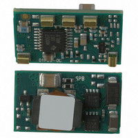
... For full details go to www.murata-ps.com/rohs Adjustable Output 3-Amp DOSA-SMT DC/DC Converters PRODUCT OVERVIEW The OKI-T/3 series are miniature non-isolated Point-of-Load (POL) DC/DC power converters for embedded applications. The module is fully compatible with Distributed-power Open Standards Alliance (DOSA) industry-standard specifi cations (www.dosapower.com). Applications include powering CPU’ ...
Page 2
... ORDERING GUIDE I OUT V (Amps Power OUT (Volts) ➅ ➁ Root Model max) (Watts) OKI-T/3-W40N-C 0.7525-5 OKI-T/3-W40P-C 0.7525-5 ➀ Dimensions are in inches (mm). ➁ These are partial model numbers. Please refer to the part number structure for complete ordering part numbers. ➂ All specifications are at nominal line voltage, Vout=nominal (5V for W40 models) and full load, +25 ˚C. unless otherwise noted. Output capacitors are 1 μ ...
Page 3
... Angles ± 1˚ Components are shown for reference only. .690 .060 .500 REF .340 .070 .180 REF 1 .340 4 5 .095 MIN .110 MAX .82 REF email: sales@murata-ps.com 27 May 2010 MDC_OKI-T/3-W40 Series.A02 Page Function On/Off Control* Positive V IN Trim Positive V OUT ...
Page 4
... Absolute Maximum Ratings 0 V.to +40 Volts max min. to +Vin max. See Fuse section Current-limited. Devices can withstand a sustained short circuit without damage. The outputs are not intended to accept appreciable reverse current. -55 to +125 ˚C. See soldering specifi cations email: sales@murata-ps.com MDC_OKI-T/3-W40 Series.A02 Page ...
Page 5
... Less than 3 ºC. per second Peak Temp. 235-260° C Reflow Zone Soaking Zone time above 217° C 45-75 sec 120 sec max Preheating Zone 240 sec max 90 120 150 180 210 240 270 Time (sec) email: sales@murata-ps.com MDC_OKI-T/3-W40 Series.A02 Page 300 ...
Page 6
... BNC connectors or the probe ground should not exceed one half- inch and soldered directly to the test circuit. www.murata-ps.com 27 May 2010 OKI-T/3-W40 Series CURRENT PROBE +INPUT C IN -INPUT email: sales@murata-ps.com MDC_OKI-T/3-W40 Series.A02 Page ...
Page 7
... Be aware too that there is a fi nite time in milliseconds (see Specifi cations) between the time of On/Off Control activation and stable, regulated output. This time will vary slightly with output load type and current and input conditions. www.murata-ps.com OKI-T/3-W40 Series email: sales@murata-ps.com 27 May 2010 MDC_OKI-T/3-W40 Series.A02 Page ...
Page 8
... Install only enough Adjustable Output 3-Amp DOSA-SMT DC/DC Converters capacitance to achieve noise objectives. Excess external capacitance may cause regulation problems, degraded transient response and possible oscilla- tion or instability. www.murata-ps.com 27 May 2010 OKI-T/3-W40 Series email: sales@murata-ps.com MDC_OKI-T/3-W40 Series.A02 Page ...
Page 9
... On/Off Enable Startup (Vin=24V, Vout=5V, Iout=3A, Cload=0) Step Load Transient Response (Vin=24V, Vout=5V, Cload=0, Iout=3A to 1.5A) Trace 2=Vout, 100 mV/div. Trace 4=Iout, 1A/div. www.murata-ps.com OKI-T/3-W40 Series = 5V, transverse airfl ow, mounted on 10" x 10" PCB). OUT 65 LFM Ambient Temperature (ºC) email: sales@murata-ps.com 27 May 2010 MDC_OKI-T/3-W40 Series.A02 Page ...
Page 10
... Effi ciency vs. Line Voltage and Load Current @ +25° 3.3V) OUT V = 16V 24V 40V IN 0.5 1 1.5 2 2.5 Load Curre nt (Amps) Step Load Transient Response (Vin=24V, Vout=3.3V, Cload=0, Iout=3A to 1.5A) Trace 2=Vout, 100 mV/div. Trace 4=Iout, 1A/div. www.murata-ps.com OKI-T/3-W40 Series 3 3.5 email: sales@murata-ps.com 27 May 2010 MDC_OKI-T/3-W40 Series.A02 Page ...
Page 11
... Effi ciency vs. Line Voltage and Load Current @ +25° 1.5V) OUT V = 16V 24V 40V IN 0.5 1 1.5 2 2.5 Load Curre nt (Amps) Step Load Transient Response (Vin=24V, Vout=1.5V, Cload=0, Iout=3A to 1.5A)Trace www.murata-ps.com OKI-T/3-W40 Series 3 3.5 2=Vout, 100 mV/div. Trace 4=Iout, 1A/div. email: sales@murata-ps.com 27 May 2010 MDC_OKI-T/3-W40 Series.A02 Page ...
Page 12
... Effi ciency vs. Line Voltage and Load Current @ +25° 1.2V) OUT V = 16V 24V 40V IN 0.5 1 1.5 2 2.5 Load Curre nt (Amps) Step Load Transient Response (Vin=24V, Vout=1.2V, Cload=0, Iout=3A to 1.5A) Trace 2=Vout, 100 mV/div. Trace 4=Iout, 1A/div. www.murata-ps.com OKI-T/3-W40 Series 3 3.5 email: sales@murata-ps.com 27 May 2010 MDC_OKI-T/3-W40 Series.A02 Page ...
Page 13
... Angles ± 1˚ Components are shown for reference only. 44.0 1.73 REF 13.00 4.00 REEL INFORMATION (400 UNITS PER REEL) email: sales@murata-ps.com 27 May 2010 MDC_OKI-T/3-W40 Series.A02 Page .365 Third Angle Projection 13.00 .512 © 2010 Murata Power Solutions, Inc. ...