LTM4619IV#PBF Linear Technology, LTM4619IV#PBF Datasheet - Page 9
LTM4619IV#PBF
Manufacturer Part Number
LTM4619IV#PBF
Description
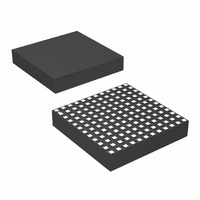
IC SWIT REG BUCK 4A ADJ 144LGA
Manufacturer
Linear Technology
Series
µModuler
Type
Point of Load (POL) Non-Isolatedr
Specifications of LTM4619IV#PBF
Design Resources
LTM4619 Spice Model
Output
0.8 ~ 5 V
Number Of Outputs
2
Power (watts)
30W
Mounting Type
Surface Mount
Voltage - Input
4.5 ~ 26.5 V
Package / Case
144-LGA
1st Output
0.8 ~ 5 VDC @ 4A
2nd Output
0.8 ~ 5 VDC @ 4A
Size / Dimension
0.59" L x 0.59" W x 0.11" H (15mm x 15mm x 2.8mm)
Power (watts) - Rated
30W
Operating Temperature
-40°C ~ 125°C
Dc To Dc Converter Type
Step Down
Pin Count
144
Input Voltage
26.5V
Output Voltage
0.8 to 5V
Switching Freq
860KHz
Output Current
4A
Package Type
LGA
Output Type
Adjustable
Switching Regulator
Yes
Load Regulation
0.8%
Line Regulation
0.3%
Mounting
Surface Mount
Input Voltage (min)
4.5V
Operating Temperature Classification
Automotive
Lead Free Status / RoHS Status
Lead free / RoHS Compliant
3rd Output
-
Lead Free Status / Rohs Status
Compliant
Available stocks
Company
Part Number
Manufacturer
Quantity
Price


applicaTions inForMaTion
The typical LTM4619 application circuit is shown in
Figure 18. External component selection is primarily deter-
mined by the maximum load current and output voltage.
Output Voltage Programming
The PWM controller has an internal 0.8V reference voltage.
As shown in the block diagram, a 60.4k internal feedback
resistor R
will default to 0.8V with no feedback resistor. Adding a
resistor R
voltage:
or equivalently
Table 1. V
V
R
Input Capacitors
The LTM4619 module should be connected to a low AC-
impedance DC source. Two 1.5µF input ceramic capacitors
are included inside the module. Additional input capacitors
are needed if a large load is required up to the 4A level. A
47µF to 100µF surface mount aluminum electrolytic bulk
capacitor can be used for more input bulk capacitance.
This bulk capacitor is only needed if the input source im-
pedance is compromised by long inductive leads, traces
or not enough source capacitance.
For a buck converter, the switching duty-cycle can be
estimated as:
OUT
SET
R
D =
V
(kΩ)
(V)
OUT
SET
V
V
OUT
=
= 0.8V •
FB
IN
FB
SET
Open
Resistor Table vs Various Output Voltages
0.8
connects V
V
0.8V
from V
60.4k
OUT
60.4k + R
121
1.2
– 1
FB
R
pin to SGND programs the output
OUT
SET
68.1
1.5
to V
SET
48.7
FB
1.8
pin. The output voltage
28.0
2.5
19.1
3.3
11.5
5
Without considering the inductor current ripple, for each
output, the RMS current of the input capacitor can be
estimated as:
In the above equation, η is the estimated efficiency of the
power module. The bulk capacitor can be a switcher-rated
electrolytic aluminum capacitor, polymer capacitor for
bulk input capacitance due to high inductance traces or
leads. One 10µF ceramic input capacitor is typically rated
for 2A of RMS ripple current, so the RMS input current
at the worst case for each output at 4A maximum current
is about 2A. If a low inductance plane is used to power
the device, then two 10µF ceramic capacitors are enough
for both outputs at 4A load and no external input bulk
capacitor is required.
Output Capacitors
The LTM4619 is designed for low output voltage ripple
noise. The bulk output capacitors defined as C
chosen with low enough effective series resistance (ESR)
to meet the output voltage ripple and transient require-
ments. C
low ESR polymer capacitor or ceramic capacitor. The typical
output capacitance range for each output is from 47µF to
220µF . Additional output filtering may be required by the
system designer. If further reduction of output ripples
or dynamic transient spikes is required, LTpowerCAD is
available for stability analysis. Multiphase operation will
reduce effective output ripple as a function of the num-
ber of phases. Application Note 77 discusses this noise
reduction versus output ripple current cancellation, but
the output capacitance should be considered carefully as
a function of stability and transient response. LTpowerCAD
calculates the output ripple reduction as the number of
implemented phases increased by N times.
I
CIN(RMS)
OUT
=
can be the low ESR tantalum capacitor, the
I
OUT(MAX)
η
• D • (1− D)
LTM4619
OUT
4619fa
9
are
Related parts for LTM4619IV#PBF
Image
Part Number
Description
Manufacturer
Datasheet
Request
R

Part Number:
Description:
Dual, 26vin, 4a Dc/dc ?module Regulator
Manufacturer:
Linear Technology Corporation
Datasheet:

Part Number:
Description:
IC SWIT REG BUCK 4A ADJ 144LGA
Manufacturer:
Linear Technology
Datasheet:

Part Number:
Description:
CD ROM LINEARVIEW DATASHEETS
Manufacturer:
Linear Technology
Part Number:
Description:
Standalone Linear Li-Ion Battery Charger with Thermal Regulation in ThinSOT
Manufacturer:
Linear Technology Corporation
Datasheet:
Part Number:
Description:
Low noise, high frequency, 8th order linear phase lowpass filter
Manufacturer:
Linear Technology Corporation
Datasheet:
Part Number:
Description:
Manufacturer:
Linear Technology Corporation
Datasheet:
Part Number:
Description:
Manufacturer:
Linear Technology Corporation
Datasheet:
Part Number:
Description:
Manufacturer:
Linear Technology Corporation
Datasheet:
Part Number:
Description:
Manufacturer:
Linear Technology Corporation
Datasheet:
Part Number:
Description:
Manufacturer:
Linear Technology Corporation
Datasheet:
Part Number:
Description:
Manufacturer:
Linear Technology Corporation
Datasheet:
Part Number:
Description:
Manufacturer:
Linear Technology Corporation
Datasheet:
Part Number:
Description:
Dual and Quad, JFET Input Precision High Speed Op Amps
Manufacturer:
Linear Technology Corporation
Datasheet:
Part Number:
Description:
Manufacturer:
Linear Technology Corporation
Datasheet:
Part Number:
Description:
1, 2, 6 and 8 Channel, 10-Bit Serial I/O Data Acquisition Systems
Manufacturer:
Linear Technology Corporation
Datasheet: