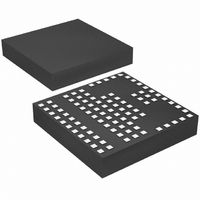
LTM4602HVIV#PBF Linear Technology, LTM4602HVIV#PBF Datasheet - Page 12

LTM4602HVIV#PBF
Manufacturer Part Number
LTM4602HVIV#PBF
Description
IC DC/DC UMODULE 6A 104-LGA
Manufacturer
Linear Technology
Series
µModuler
Type
Point of Load (POL) Non-Isolatedr
Datasheet
1.LTM4602HVEVPBF.pdf
(24 pages)
Specifications of LTM4602HVIV#PBF
Design Resources
LTM4602HV Spice Model
Output
0.6 ~ 5 V
Number Of Outputs
1
Power (watts)
30W
Mounting Type
Surface Mount
Voltage - Input
4.5 ~ 28 V
Package / Case
104-LGA
1st Output
0.6 ~ 5 VDC @ 6A
Size / Dimension
0.59" L x 0.59" W x 0.11" H (15mm x 15mm x 2.8mm)
Power (watts) - Rated
30W
Operating Temperature
-40°C ~ 85°C
Efficiency
92%
Lead Free Status / RoHS Status
Lead free / RoHS Compliant
3rd Output
-
2nd Output
-
Available stocks
Company
Part Number
Manufacturer
Quantity
Price
APPLICATIO S I FOR ATIO
LTM4602HV
After the controller has been started and given adequate
time to charge up the output capacitor, C
short-circuit timer. After the RUN/SS pin charges above 4V,
if the output voltage falls below 75% of its regulated value,
then a short-circuit fault is assumed. A 1.8µA current then
begins discharging C
the RUN/SS pin drops to 3.5V, then the controller turns
off both power MOSFETs, shutting down the converter
permanently. The RUN/SS pin must be actively pulled
down to ground in order to restart operation.
The over-current protection timer requires the soft-start
timing capacitor C
that the output is in regulation by the time C
the 4V threshold. In general, this will depend upon the size
of the output capacitance, output voltage and load current
characteristic. A minimum external soft-start capacitor
can be estimated from:
Generally 0.1µF is more than suffi cient.
Since the load current is already limited by the current mode
control and current foldback circuitry during a short circuit,
overcurrent latchoff operation is NOT always needed or
desired, especially if the output has large capacitance or
the load draws high current during start-up. The latchoff
feature can be overridden by a pull-up current greater than
5µA but less than 80µA to the RUN/SS pin. The additional
current prevents the discharge of C
also shortens the soft-start period. Using a resistor from
RUN/SS pin to V
pull-up network must be able to maintain RUN/SS above
12
C
SS EXT
_
+
1000
IN
is a simple solution to defeat latchoff. Any
SS
U
pF
SS
be made large enough to guarantee
. If the fault condition persists until
>
C
U
OUT
•
V
OUT
W
SS
(
10
during a fault and
–
SS
3
SS
[ /
F V
is used as a
has reached
U
S
])
4V maximum latchoff threshold and overcome the 4µA
maximum discharge current. Figure 3 shows a conceptual
drawing of V
1.5V
SWITCHING
STARTS
Figure 3. RUN/SS Pin Voltage During Startup and
Short-Circuit Protection
Figure 4. Defeat Short-Circuit Latchoff with a Pull-Up
Resistor to V
OF I
3V
SOFT-START
CLAMPING
L
RELEASED
RUN
4V
RECOMMENDED VALUES FOR R
IN
V
during startup and short circuit.
IN
500k
SHORT-CIRCUIT
LATCH ARMED
10.8V TO 13.8V
4.5V TO 5.5V
24V TO 28V
V
V
O
IN
V
RUN/SS
V
RUN/SS
IN
PGND SGND
LTM4602HV
OVERLOAD
HAPPENS
OUTPUT
R
RUN/SS
150k
500k
50k
RUN/SS
4602HV F04
SHORT-CIRCUIT
75%V
LATCHOFF
O
4602hvf
4602HV F03
3.5V
t
t


