RND02ZGE-M6 POWER ONE, RND02ZGE-M6 Datasheet
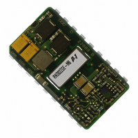
RND02ZGE-M6
Specifications of RND02ZGE-M6


Related parts for RND02ZGE-M6


RND02ZGE-M6 Summary of contents
Page 1
... Model Selection Input Model Voltage, VDC 38-75 RND02ZGE-M6 38-75 RND02ZGG-M6 36-75 RND0.8ZHH-M6 *Output voltage with trim adjustment Model numbers highlighted in yellow or shaded are not recommended for new designs. MCD10214 Rev. 1.0, 20-Aug-10 RND DC-DC Series Data Sheet 10W SMT Converter ...
Page 2
Absolute Maximum Ratings Stresses in excess of the absolute maximum ratings may cause performance degradation, adversely affect long term reliability and cause permanent damage to the converter. Specifications apply over specified input voltage, output load and temperature range, unless otherwise ...
Page 3
... Cross Regulation Dynamic Regulation Peak Deviation Settling Time Output Voltage Ripple Admissible Load Cap. Output Current Limit Threshold Switching Frequency Temperature Coeff. Trim Range RND02ZGE: (Vo2) 3.27V/1.0A Parameter Output Voltage Vo Setpoint Accuracy Output Current * Io Line Regulation Load Regulation Cross Regulation Dynamic Regulation ...
Page 4
... RND02ZGE Typical Characteristic Curves Cross Regulation Output 1 (+5V 0.8 0.6 0.4 0 0.2 0.4 0.6 3.3V Output Current (A) Output Vo1 Vs Load 7.0 6.0 5.0 4.0 3.0 Vin Min 2.0 Vin Nom Vin Max 1.0 0.0 0.0 0.1 0.3 0.5 0.8 1.0 1.2 1.4 1.6 1.8 2.0 ...
Page 5
Output Specifications All specifications apply over input voltage, output load and temperature range, unless otherwise noted. RND02ZGG: (Vo1) +5.1V/0.75A Parameter Output Voltage Vo Setpoint Accuracy Output Current * Io Line Regulation Load Regulation Cross Regulation Dynamic Regulation Peak Deviation Settling ...
Page 6
RND02ZGG Typical Characteristic Curves Output Vo1 Vs Load 7.0 6.0 5.0 4.0 3.0 Vin Min 2.0 Vin Nom Vin Max 1.0 0.0 0.0 0.1 0.3 0.5 0.8 1.0 Output Current (A) Efficiency 100% 90% 80% 70% 60% 50% 40% 30% ...
Page 7
Output Specifications All specifications apply over input voltage, output load and temperature range, unless otherwise noted. RND0.8ZHH: (Vo1) +12.0V/0.42A Parameter Output Voltage Vo Setpoint Accuracy Output Current * Io Line Regulation Load Regulation Cross Regulation Dynamic Regulation Peak Deviation Settling ...
Page 8
RND0.8ZHH Typical Characteristic Curves Vo1 Vs Output Load Vin Vin Nom 2 Vin 0.00 0.1 1 0.32 0.50 Output Curremt (A) Vo1 Cross Regulation 12.25 12.20 ...
Page 9
Feature Specifications All specifications apply over input voltage, output load and temperature range, unless otherwise noted. Parameter Remote Control: Converter OFF Converter ON Sink Current [RND0.8ZHH model only] Synchronization: Frequency Range Temperature Derating Curves The derating curves below give an ...
Page 10
... KOhm 1 600 The voltage at 1 400 1 200 1 000 800 600 400 200 0 RND02ZGE - Resistance required to increase KOhm 1600 1400 1200 1000 800 600 400 200 0 36.05 Page RND0.8ZHH - Resistance required to decrease Vion 33.66 33. ...
Page 11
... To increase Vo: Radj = Vd) / (Vd - Vo), k Where Desired output voltage Vo = Nominal output voltage. To reduce Vo: Radj = C x (Vo - Vd) / (Vd - D), k Where Desired output voltage Vo = Nominal output voltage. Model A B RND02ZGE 0.5 3.92 RND02ZGG 0.5 7.1 2.243 RND0.8ZHH 0.572 16.126 2.243 Notes: 1. When the output voltage is trimmed up, the output power from the converter must not exceed its maximum rating ...
Page 12
Safety Considerations These converters feature 1500 VDC isolation from input to output. The input-to-output resistance is greater than 10MΩ. These converters are provided with Basic Insulation between input and output circuits according to EN60950 CSA60950-00. Nevertheless, if the system using ...
Page 13
Surface Mount Assembly Soldering: The following instructions must be observed when soldering the unit. Failure to observe these instructions may result in failure or significant degradation of the module performance. Power-One will not honor any warranty claims arising from failure ...
Page 14
Mechanical Drawing MCD10214 Rev. 1.0, 20-Aug-10 RND DC-DC Series Data Sheet 10W SMT Converter 3.3V & ±15V Dual Page Note:- mm[inches] Tolerances: - 0.5-10 ±0.1 10-100 ±0.2 www.power-one.com ...
Page 15
MCD10214 Rev. 1.0, 20-Aug-10 10W SMT Converter 3.3V & ±15V Dual 322.6 315 JEDEC TRAY Page RND DC-DC Series Data Sheet 12.19 www.power-one.com ...
Page 16
Pinout Pin Designation 1 Vout1 2 Rtn 3 Vout2 Sync 8 Trim Note set nominal output voltage connect pins 8 and 9 together 9 NOR 10 TOA ...