APA501-80-001 Emerson Network Power, APA501-80-001 Datasheet - Page 11
APA501-80-001
Manufacturer Part Number
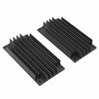
APA501-80-001
Description
HEATSINK (80) 115X59X15MM VERT
Manufacturer
Emerson Network Power
Specifications of APA501-80-001
Accessory Type
Heat Sink
Product
Heatsinks
Mounting Style
Screw
Fin Style
Vertical
Thermal Resistance
2.7 C / W
Dimensions
115 mm L x 59 mm W x 15 mm H
Designed For
AMPSS 80 Modules
Color
Black
For Use With/related Products
AMPSS®
Lead Free Status / RoHS Status
Lead free / RoHS Compliant
Lead Free Status / RoHS Status
Lead free / RoHS Compliant


Thermal Design Process and Example
Temperature & MTBF
APMSS modules are designed to be able to run at
baseplate temperatures of 100 C in the case of the
AM80 series and 85 C for other series. However, for
normal operation the modules should not be run at
the maximum allowable temperature since the Mean
Time Between Failures (MTBF) will reduce sharply
as temperature increases. For example, an
AM80-300L-050F40 operating at 5V@40A output,
with a baseplate temperature of 50 C, has an MTBF
of over one million hours. If the temperature is
doubled to 100 C this figure drops to 155,000 hours.
The following rules should be followed to ensure
reliable operation -
The Thermal Design Process
Thermal Design Example
This example is for the following parameters:
•
•
1. Determine heat generated by module from its
2. Determine maximum baseplate temperature
3. Define maximum system baseplate tempera-
4. Select/design heatsink and airflow require-
5. Test using the APMSS imbedded TEMP-MON
• Single 5V AM80 module used in a distributed
• Average load 30A (150 Watts)
• Normal operating ambient temperature 25 C
• Maximum ambient temperature 60 C
• MTBF required - 800,000 hours (from system
• Efficiency measured at 83% (Efficiency =
Rev. 01 Jan 96
At the maximum system ambient tempera-
ture the APMSS baseplate temperature
rating should not be exceeded.
At the normal system ambient operating
temperature the APMSS baseplate tem-
perature must be low enough to meet MTBF
requirements.
losses. The minimum efficiency at relevant line
and load conditions should be used in calculat-
ing the losses.
rise to stay within module temperature rating
at maximum system ambient.
ture to meet MTBF in normal system operating
conditions or at the temperature at which the
MTBF is specified.
ment.
feature which allows direct and convenient
monitoring of baseplate temperature. (BM/AM/
AL/AK Series)
power system.
requirements)
Output power/ Input power)
1. Heat generated = Power Out x [(1/Efficiency)-1]
2. Maximum baseplate temperature 100 C (from
AM80 specifications).
baseplate temperature rise is 40 C.
3. To achieve 800,000 hours MTBF, baseplate
temperature must not exceed 61 C.
operating ambient) is 36 C.
4. Choose the lowest temperature rise of
36 C.
The cooling system must dissipate 31 Watts with a
maximum baseplate temperature rise of 36 C.
To ensure good thermal contact Astec recommends
the use of Thermstrate
Thermal resistance of the Thermstrate
between baseplate and heatsink is 0.1 C/W.
For this example (overall thermal resistance 1.16 C/
W) the heatsink thermal resistance should be a
maximum of 1.06 C/W. A 10% safety margin is
desirable so a heatsink achieving 0.95 C/W is
chosen.
To achieve this level of cooling using natural convec-
tion would require an very large heatsink. It would
therefore be better to employ forced air cooling. A
thermal resistance vs air flow characteristic should
be referenced to determine the required airflow for
the heatsink you are using.
Thermal resistance = 36/31 = 1.16 C/Watt.
At 60 C (max. ambient temp.) the maximum
Maximum baseplate temperature rise (from 25 C
AMPSS
= 150 x [(1/0.83)-1]
= 31 Watt
®
thermal mounting pads.
®
Reference Manual
®
interface
or
i.e.
11
Related parts for APA501-80-001
Image
Part Number
Description
Manufacturer
Datasheet
Request
R

Part Number:
Description:
HEATSINK (80) 115X59X37MM HORZ
Manufacturer:
Emerson Network Power
Datasheet:

Part Number:
Description:
HEATSINK (60) 57.5X59X15MM HORZ
Manufacturer:
Emerson Network Power
Datasheet:
Part Number:
Description:
HEATSINK (60) 57.5X59X15MM VERT
Manufacturer:
Emerson Network Power
Datasheet:

Part Number:
Description:
HEATSINK (60)57.2X89X12MM LO PRO
Manufacturer:
Emerson Network Power
Datasheet:
Part Number:
Description:
HEATSINK (60)57.5X59X22.5MM HORZ
Manufacturer:
Emerson Network Power
Datasheet:

Part Number:
Description:
HEATSINK (60)57.5X59X22.5MM VERT
Manufacturer:
Emerson Network Power
Datasheet:
Part Number:
Description:
HEATSINK (80) 115X59X15MM HORZ
Manufacturer:
Emerson Network Power
Datasheet:
Part Number:
Description:
HEATSINK (60) 57.5X59X37MM VERT
Manufacturer:
Emerson Network Power
Datasheet:
Part Number:
Description:
HEATSINK (60) 57.5X59X37MM HORZ
Manufacturer:
Emerson Network Power
Datasheet:
Part Number:
Description:
HEATSINK (80) 115X59X22.5MM HORZ
Manufacturer:
Emerson Network Power
Datasheet:
Part Number:
Description:
AC/DC Front end 12Vo 36A 12Vsb Standard Airflow
Manufacturer:
Emerson Network Power

Part Number:
Description:
POWER SUPPLY DIN 24VDC 10A
Manufacturer:
Emerson Network Power
Datasheet:

Part Number:
Description:
POWER SUPPLY SGL 48VOUT 40W 3X5"
Manufacturer:
Emerson Network Power
Datasheet:

Part Number:
Description:
POWER SUP MED&ITE 48V 45W 2"X4"
Manufacturer:
Emerson Network Power
Datasheet:

Part Number:
Description:
POWER SUPPLY 60W 12V OUT
Manufacturer:
Emerson Network Power
Datasheet: