LE AB H3AB-JBLA-1+EWFW-23 OSRAM Opto Semiconductors Inc, LE AB H3AB-JBLA-1+EWFW-23 Datasheet - Page 13
LE AB H3AB-JBLA-1+EWFW-23
Manufacturer Part Number
LE AB H3AB-JBLA-1+EWFW-23
Description
LED OSTAR PROJ 6CHIP AMB/BLU SMD
Manufacturer
OSRAM Opto Semiconductors Inc
Series
Ostarr
Type
With Connectorr
Datasheet
1.LE_AB_H3AB-JBLA-1EWFW-23.pdf
(17 pages)
Specifications of LE AB H3AB-JBLA-1+EWFW-23
Color
Amber, Blue
Luminous Flux @ Current - Test
326 lm Amber, 40 lm Blue
Current - Test
6 x 1A
Current - Max
6 x 1A
Driver Circuitry
No
Voltage
2.8V Amber, 4.0V Blue
Wavelength
617nm, 464nm
Configuration
Single
With Connector
Yes
Voltage - Input
2.8V Amber, 4.0V Blue
Power - Input
15.5W Amber, 10W Blue
Lead Free Status / RoHS Status
Lead free / RoHS Compliant
Interface
-
Other names
475-1283
Q65110A6243
Q65110A6243


LE AB H3AB
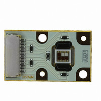
Connecting and disconnecting OSRAM OS Ostar Projection modules
When connecting or disconnecting an Ostar Projection module care has to be taken in order to prevent
a damage of the module. The module is equipped with a male connector socket (JST SM 10B-SR
SS-TB). As a female connector for power supply a JST SHR-10V-S (without protrusions) or a JST
SHR-10V-S-B (with protrusions) with SSH-003T-P0.2 pins is recommended.
When disconnecting the connector the applied pull force must not exceed 17 N * (footnote * A force of
17 N can only be applied dynamically during disconnecting. No constant force must be applied to the
connector.) Disconnection of the module during operation or at high temperatures can damage the
module. The board temperature must not exceed 40°C during disconnection. During mating operation,
mate connectors while holding wires in a bundle on the same axis to the mating axis. For unmating wires
must be held in a bundle within 20 degrees to the mating axis (see Fig. for explanation).
Connector
20˚
Wire
PCB
20˚
20˚
Wire
Connector
PCB
OHO03020
2008-07-07
13
Related parts for LE AB H3AB-JBLA-1+EWFW-23
Image
Part Number
Description
Manufacturer
Datasheet
Request
R

Part Number:
Description:
INTELLIGENT DISP 4CHAR 5X7 HERED
Manufacturer:
OSRAM Opto Semiconductors Inc
Datasheet:

Part Number:
Description:
DISPLAY 8DIGIT CERAMIC GREEN
Manufacturer:
OSRAM Opto Semiconductors Inc
Datasheet:

Part Number:
Description:
EMITTER IR 950NM 5MM SMD RADIAL
Manufacturer:
OSRAM Opto Semiconductors Inc
Datasheet:

Part Number:
Description:
LED TOPLED GREEN 570NM 2-PLCC
Manufacturer:
OSRAM Opto Semiconductors Inc
Datasheet:

Part Number:
Description:
INTERRUPTER RELFECT W/FILTR SMD
Manufacturer:
OSRAM Opto Semiconductors Inc
Datasheet:

Part Number:
Description:
LED Displays 5x7 Green 0.145 , 4-CHARACTER
Manufacturer:
OSRAM Opto Semiconductors Inc
Datasheet:

Part Number:
Description:
Q65110A4321_SIDELED PURE GREEN EOL150407
Manufacturer:
OSRAM Opto Semiconductors Inc
Datasheet:
Part Number:
Description:
Q65110A1202_RO DETECTOR 3/5MM_TR_RO
Manufacturer:
OSRAM Opto Semiconductors Inc
Datasheet:

Part Number:
Description:
PHOTODIODE 900NM 3MM W/FILTER
Manufacturer:
OSRAM Opto Semiconductors Inc
Datasheet:

Part Number:
Description:
LED MULTI CHIP ON BRD AMBER/BLUE
Manufacturer:
OSRAM Opto Semiconductors Inc
Datasheet:

Part Number:
Description:
LED OSTAR AMBER 4CHIP SMD
Manufacturer:
OSRAM Opto Semiconductors Inc
Datasheet:

Part Number:
Description:
LED OSTAR AMB/GRN/BLU SMD
Manufacturer:
OSRAM Opto Semiconductors Inc
Datasheet:

Part Number:
Description:
LED OSTAR BLUE 4CHIP SMD
Manufacturer:
OSRAM Opto Semiconductors Inc
Datasheet:

Part Number:
Description:
LED OSTAR GREEN 4CHIP SMD
Manufacturer:
OSRAM Opto Semiconductors Inc
Datasheet: