HLMP-D105 Avago Technologies US Inc., HLMP-D105 Datasheet - Page 3
HLMP-D105
Manufacturer Part Number
HLMP-D105
Description
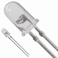
LED 5MM 645NM RED WATER CLEAR
Manufacturer
Avago Technologies US Inc.
Specifications of HLMP-D105
Viewing Angle
24°
Package / Case
Radial - 2 Lead
Color
Red
Millicandela Rating
240mcd
Current - Test
20mA
Wavelength - Dominant
637nm
Wavelength - Peak
645nm
Voltage - Forward (vf) Typ
1.8V
Lens Type
Clear
Lens Style/size
Round, 5mm, T-1 3/4
Height
8.81mm
Mounting Type
Through Hole
Resistance Tolerance
637nm
Led Size
T-1 3/4
Illumination Color
Red
Lens Color/style
Untinted Non-Diffused
Operating Voltage
1.8 V
Wavelength
637 nm
Luminous Intensity
240 mcd
Operating Current
20 mA
Lens Dimensions
5 mm
Lens Shape
Dome
Maximum Operating Temperature
+ 100 C
Minimum Operating Temperature
- 20 C
Mounting Style
Through Hole
Color, Emitted
Red
Color, Lens
Clear
Current Rating
30 mA (DC)
Current, Forward
20 mA
Package Type
5 mm (T-13⁄4)
Temperature, Operating, Maximum
100 °C
Temperature, Operating, Minimum
-20 °C
Voltage, Reverse
5 V
Wavelength, Peak
645 nm
Lead Free Status / RoHS Status
Lead free / RoHS Compliant
Luminous Flux @ Current - Test
-
Lead Free Status / Rohs Status
Lead free / RoHS Compliant
Other names
516-1344
Available stocks
Company
Part Number
Manufacturer
Quantity
Price
Company:

Part Number:
HLMP-D105
Manufacturer:
FAIRCHIL
Quantity:
40 000
Company:
Part Number:
HLMP-D105
Manufacturer:
AVAGO
Quantity:
50 000
Company:
Part Number:
HLMP-D105-M0002
Manufacturer:
AVAGO
Quantity:
40 000
Company:
Part Number:
HLMP-D105-M0002
Manufacturer:
AVAGO
Quantity:
50 000
Company:
Part Number:
HLMP-D105-NO000
Manufacturer:
AVAGO
Quantity:
40 000


Absolute Maximum Ratings at T
Notes:
1. Maximum I
2. Refer to Figure 6 to establish pulsed operating conditions.
3. Derate linearly as shown in Figure 5.
4. The transient peak current is the maximum non-recurring peak current the device can withstand without damaging the LED die and wire bonds.
Electrical/Optical Characteristics at T
Notes:
1. The dominant wavelength, λ
2. The radiant intensity, I
3. HLMP-D101.
4. HLMP-D105.
5. HLMP-K101/-K105.
3
Parameter
Peak Forward Current
Average Forward Current
DC Current
Power Dissipation
Reverse Voltage (I
Transient Forward Current (10 μs Pulse)
LED Junction Temperature
Operating Temperature Range
Storage Temperature Range
Symbol
V
V
λ
λ
Δλ
τ
C
Rθ
η
S
p
d
F
R
V
It is not recommended that the device be operated at peak currents beyond the Absolute Maximum Peak Forward Current.
J-PIN
luminous efficacy in lumens/watt.
1
/
2
[3]
PEAK
Description
Forward Voltage
Reverse Breakdown Voltage
Peak Wavelength
Dominant Wavelength
Spectral Line Halfwidth
Speed of Response
Capacitance
Thermal Resistance
Luminous Efficacy
at f = 1 kHz, DF = 6.7%.
R
= 100 μA)
[1,2]
e
, in watts per steradian, may be found from the equation I
[2]
d
, is derived from the CIE chromaticity diagram and represents the color of the device.
A
= 25°C
A
= 25°C
[4]
Min.
5.0
Typ.
1.8
15.0
645
637
20
30
30
260
210
290
80
[3]
[4]
[5]
e
= l
Max.
2.2
V
/η
V
, where I
V
is the luminous intensity in candelas and η
Unit
V
V
nm
pF
nm
nm
ns
°C/W
Im/W
Value
300 mA
20 mA
30 mA
87 mW
5 V
500 mA
110°C
-20 to +100°C
-40 to +100°C
Test Condition
I
I
Measurement at Peak
Note 1
Exponential Time
Constant, e
V
Junction to Cathode
Lead
Note 2
F
R
F
= 20 mA
= 100 μA
= 0, f = 1 MHz
-t
/T
S
V
is
Related parts for HLMP-D105
Image
Part Number
Description
Manufacturer
Datasheet
Request
R

Part Number:
Description:
Standard LED - Through Hole Red 23deg d 23deg
Manufacturer:
Avago Technologies US Inc.
Part Number:
Description:
Standard LED - Through Hole Red 30deg d 30deg
Manufacturer:
Avago Technologies US Inc.
Part Number:
Description:
Standard LED - Through Hole Red 30deg d 30deg
Manufacturer:
Avago Technologies US Inc.
Part Number:
Description:
Standard LED - Through Hole Red 30deg d 30deg
Manufacturer:
Avago Technologies US Inc.

Part Number:
Description:
Standard LED - Through Hole AlInGaP2 Red d 30X70deg
Manufacturer:
Avago Technologies US Inc.
Part Number:
Description:
Standard LED - Through Hole Red 30deg d 30deg
Manufacturer:
Avago Technologies US Inc.

Part Number:
Description:
Standard LED - Through Hole AlInGaP2 Red d 30X70deg
Manufacturer:
Avago Technologies US Inc.
Datasheet:

Part Number:
Description:
Standard LED - Through Hole Red 40x100deg d 40X100deg
Manufacturer:
Avago Technologies US Inc.
Part Number:
Description:
Standard LED - Through Hole Red 30deg d 30deg
Manufacturer:
Avago Technologies US Inc.
Part Number:
Description:
Standard LED - Through Hole Red 30deg d 30deg
Manufacturer:
Avago Technologies US Inc.
Part Number:
Description:
Standard LED - Through Hole AlInGaP2 Red d 30X70deg
Manufacturer:
Avago Technologies US Inc.
Datasheet:
Part Number:
Description:
Standard LED - Through Hole Red 30deg d 30deg
Manufacturer:
Avago Technologies US Inc.
Part Number:
Description:
Standard LED - Through Hole Red 30deg d 30deg
Manufacturer:
Avago Technologies US Inc.
Part Number:
Description:
Standard LED - Through Hole Red 15deg d 15deg
Manufacturer:
Avago Technologies US Inc.
Datasheet:
Part Number:
Description:
Standard LED - Through Hole Red 23deg d 23deg
Manufacturer:
Avago Technologies US Inc.