HLMP-D150-C00B2 Avago Technologies US Inc., HLMP-D150-C00B2 Datasheet
HLMP-D150-C00B2
Specifications of HLMP-D150-C00B2
HLMP-D150-C00B2
Available stocks


Related parts for HLMP-D150-C00B2


HLMP-D150-C00B2 Summary of contents
Page 1
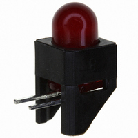
... HLMP-D150, HLMP-D155, HLMP-K150 and HLMP-K155 T-13/4 (5 mm), T-1 (3 mm), Low Current, Double Heterojunction AlGaAs Red LED Lamps Data Sheet Description These solid state LED lamps utilize double heterojunction (DH) AlGaAs/GaAs material technology. This LED material has outstanding light output efficiency at very low drive currents ...
Page 2
... T-1 3/4 Red Untinted Non-diffused T-1 Red Tinted Diffused T-1 Red Untinted Non-diffused Note: 1. θ is the off axis angle from lamp centerline where the luminous intensity is 1/2 Part Numbering System HLMP - Luminous Intensity Iv (mcd Device HLMP- Min. D150 1.3 D150-C00xx 1 ...
Page 3
... V Notes: 1. The dominant wavelength, λ derived from the CIE chromaticity diagram and represents the color of the device The radiant intensity watts per steradian, may be found from the equation I e luminous efficacy in lumens/watt. 3. HLMP-D150. 4. HLMP-D155. 5. HLMP-K150/-K155. 3 Value 300 500 mA 110°C -20 to +100° ...
Page 4
... Figure 1. Relative intensity vs. wavelength. Figure 3. Relative luminous intensity vs. dc forward current. Figure 5. Relative luminous intensity vs. angular displacement. HLMP-D150. 4 Figure 2. Forward current vs. forward voltage. Figure 4. Maximum forward dc current vs. ambient temperature. Derating based on TJ Max. = 110 °C. Figure 6. Relative luminous intensity vs. angular displacement. HLMP-K150. ...
Page 5
... T 2400.0 U 3400.0 V 4900.0 W 7100.0 X 10200.0 Y 14800.0 Z 21400.0 Note: Maximum tolerance for each bin limit is r 18%. 5 Figure 8. Relative luminous intensity vs. angular displacement. HLMP-K155. Max. 2.4 3.8 6.1 9.7 15.5 24.8 39.6 63.4 101.5 162.4 234.6 340.0 540.0 850.0 1200.0 1700.0 2400 ...
Page 6
Mechanical Option Matrix Mechanical Option Code Note: All categories are established for classification of products. Products may not be available in all categories. Please contact your local Avago representative for further ...
Page 7
Precautions: Lead Forming: x The leads of an LED lamp may be preformed or cut to length prior to insertion and soldering on PC board. x For better control recommended to use proper tool to precisely form and ...
Page 8
Example of Wave Soldering Temperature Profile for TH LED TURBULENT WAVE 250 200 150 100 50 PREHEAT Packaging Label: (i) Avago Mother Label: (Available on packaging box of ammo pack and shipping box) 8 LAMINAR ...
Page 9
Avago Baby Label (Only available on bulk packaging) /DPSV %DE\ /DEHO For product information and a complete list of distributors, please go to our web site: Avago, Avago Technologies, and the A logo are trademarks of Avago Technologies in ...