HSMF-C118 Avago Technologies US Inc., HSMF-C118 Datasheet - Page 3
HSMF-C118
Manufacturer Part Number
HSMF-C118
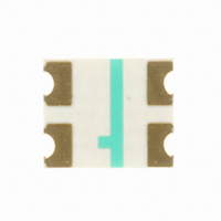
Description
LED CHIP RGB 3.2X2.7X1.1MM SMD
Manufacturer
Avago Technologies US Inc.
Datasheet
1.HSMF-C118.pdf
(8 pages)
Specifications of HSMF-C118
Package / Case
1210 (3225 Metric)
Viewing Angle
135°, 130°, 125°
Color
Red, Green, Blue (RGB)
Millicandela Rating
90mcd Red, 120mcd Green, 40mcd Blue
Current - Test
20mA
Wavelength - Dominant
626nm, 525nm, 470nm
Wavelength - Peak
637nm, 523nm, 468nm
Voltage - Forward (vf) Typ
1.9V Red, 3.5V Green, 3.5V Blue
Lens Type
Diffused
Lens Style/size
Rectangle, 2.7mm x 2mm
Size / Dimension
3.20mm L x 2.70mm W
Height
1.10mm
Mounting Type
Surface Mount
Resistance Tolerance
626nm, 525nm, 470nm
Led Size
3.2 mm x 2.7 mm
Illumination Color
Red, Green, Blue
Lens Color/style
Diffused
Operating Voltage
1.9 V, 3.5 V, 3.5 V
Wavelength
626 nm, 525 nm, 470 nm
Luminous Intensity
40 mcd, 120 mcd, 40 mcd
Mounting Style
SMD/SMT
Bulb Size
2mm X 2.7mm
Led Color
Red / Green / Blue
Luminous Intensity / Color
R 90mcd / G 120mcd/ B 40mcd
Forward Voltage / Color
R 1.9V / G 3.5V / B 3.5V
Led Mounting
SMD
Rohs Compliant
Yes
Lead Free Status / RoHS Status
Lead free / RoHS Compliant
Luminous Flux @ Current - Test
-
Lead Free Status / Rohs Status
Lead free / RoHS Compliant
Other names
516-1778-2
HSMF-C118
HSMF-C118
Available stocks
Company
Part Number
Manufacturer
Quantity
Price
Company:

Part Number:
HSMF-C118
Manufacturer:
AVAGO
Quantity:
50 000
Company:
Part Number:
HSMF-C118-000L5
Manufacturer:
AVAGO
Quantity:
40 000


3
Absolute Maximum Ratings at T
Parameter
DC Forward Current
Power Dissipation
DC Forward Current
Power Dissipation
Reverse Voltage (I
LED Junction Temperature
Operating Temperature Range
Storage Temperature Range
Soldering Temperature
Notes:
1. Applies when single LED is lit up.
2. Applies when all 3 LEDs are lit up simultaneously.
3. Derate linearly as shown in Figure 4.
4. Drive currents above 5 mA are recommended for best long term performance.
Electrical Characteristics at T
Color
AlInGaP Red
InGaN Green
InGaN Blue
Optical Characteristics at T
Color
AlInGaP Red
InGaN Green
InGaN Blue
Notes:
1. The luminous intensity, I
2. The dominant wavelength, λ
3. θ
1/2
is the off-axis angle where the luminous intensity is 1/2 the peak intensity.
[1]
[2]
R
[1, 3, 4]
[2]
= 100 µA)
v
, is measured at the peak of the spatial radiation pattern which may not be aligned with the mechanical axis of the lamp package.
d
Luminous Intensity
I
Min.
28.5
45.0
11.2
v
, is derived from the CIE Chromatically Diagram and represents the perceived color of the device.
(mcd) @ I
Forward Voltage
V
Typ.
1.9
3.5
3.5
F
A
(Volts) @ I
= 25°C
A
= 25°C
F
Typ.
90
120
40
= 20 mA
A
= 25°C
F
Max.
2.4
3.9
3.9
= 20 mA
[1]
AlInGaP Red
20
48
15
36
5
95
See reflow soldering profile (Figures 6 & 7)
Peak
Wavelength
λ
Typ.
637
523
468
peak
(nm)
Reverse
Breakdown
V
@ I
Min.
5
5
5
R
(Volts)
R
= 100 µA
InGaN Green
20
78
15
59
5
95
–30 to +85
–40 to +85
Color,
Dominant
Wavelength
λ
Typ.
626
525
470
d
[2]
(nm)
Capacitance
C (pF), @ V
Typ.
17
110
110
f = 1 MHz
InGaN Blue
20
78
15
59
5
95
Viewing Angle
2 θ
Typ.
135
130
125
F
1/2
= 0,
Degrees
[3]
Thermal
Resistance
Rθ
Typ.
400
450
450
Units
mA
mW
mA
mW
V
°C
°C
°C
J-PIN
Luminous
Efficacy
η
Typ.
155
490
80
v
(lm/W)
(°C/W)
Related parts for HSMF-C118
Image
Part Number
Description
Manufacturer
Datasheet
Request
R

Part Number:
Description:
LED CHIP GAP GREEN/YELLOW SMD
Manufacturer:
Avago Technologies US Inc.
Datasheet:

Part Number:
Description:
LED BICOLOR YLW/GN DIFF 1210 SMD
Manufacturer:
Avago Technologies US Inc.
Datasheet:

Part Number:
Description:
LED CHIP GRN/ORN 3.2X2.7MM SMD
Manufacturer:
Avago Technologies US Inc.
Datasheet:

Part Number:
Description:
LED IND RED/GRN TOP MOUNT 4PLCC
Manufacturer:
Avago Technologies US Inc.
Datasheet:
Part Number:
Description:
LED IND YLW/YGRN TOP MOUNT 4PLCC
Manufacturer:
Avago Technologies US Inc.
Datasheet:
Part Number:
Description:
LED CHIP RGB 2.5X1.0X1.0MM SMD
Manufacturer:
Avago Technologies US Inc.
Datasheet:

Part Number:
Description:
LED CHIPLED AMB/BLUE DIFF 0603
Manufacturer:
Avago Technologies US Inc.
Datasheet:
Part Number:
Description:
LED CHIPLED RED/GRN DIFF 0603
Manufacturer:
Avago Technologies US Inc.
Datasheet:
Part Number:
Description:
LED RED/GREEN/BLUE 40MCD 5V SMD
Manufacturer:
Avago Technologies US Inc.
Datasheet:
Part Number:
Description:
Standard LED - SMD Red/YGrn/Blue Tri-Color
Manufacturer:
Avago Technologies US Inc.
Datasheet:

Part Number:
Description:
LED BICOLOR GN/HER DIFF 1210 SMD
Manufacturer:
Avago Technologies US Inc.
Datasheet:

Part Number:
Description:
LED BICOLOR HER/GN DIFF 0603 SMD
Manufacturer:
Avago Technologies US Inc.
Datasheet:
Part Number:
Description:
LED IND RED/YLW TOP MOUNT 4PLCC
Manufacturer:
Avago Technologies US Inc.
Datasheet:
Part Number:
Description:
LED IND RED/EGRN TOP MOUNT 4PLCC
Manufacturer:
Avago Technologies US Inc.
Datasheet:
Part Number:
Description:
LED IND ORN/YGRN TOP MOUNT 4PLCC
Manufacturer:
Avago Technologies US Inc.
Datasheet: