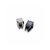
HFBR-1528 Avago Technologies US Inc., HFBR-1528 Datasheet - Page 2

HFBR-1528
Manufacturer Part Number
HFBR-1528
Description
XMITTER OPT HI PERFORMANCE HORZ
Manufacturer
Avago Technologies US Inc.
Datasheet
1.HFBR-2528.pdf
(8 pages)
Specifications of HFBR-1528
Wavelength
650nm
Spectral Bandwidth
21nm
Voltage - Forward (vf) Typ
2.1V
Current - Dc Forward (if)
60mA
Voltage - Dc Reverse (vr) (max)
3V
Capacitance
60pF
Connector Type
Versatile Link
Function
High Preformance Link Transmitter, High Voltage Transient, Reduces Voltage Transient Susceptibility.
Product
Transmitter
Data Rate
40 MBd
Diode Capacitance
60 pF
Maximum Rise Time
13 ns
Maximum Fall Time
10 ns
Operating Supply Voltage
4.75 V to 5.25 V
Maximum Operating Temperature
+ 85 C
Minimum Operating Temperature
- 40 C
For Use With
Plastic Optical Fiber
Lead Free Status / RoHS Status
Lead free / RoHS Compliant
Available stocks
Company
Part Number
Manufacturer
Quantity
Price
Company:
Part Number:
HFBR-1528Z
Manufacturer:
AVAGO
Quantity:
784
Notes:
1. Typical data at +25°C, V
2. With recommended transmitter and receiver application circuits (60 mA nominal drive current).
3. POF is HFBR-R/EXXYYY plastic (1 mm) optical fiber. Worst case attenuation used (0.23 dB/m from -40°C to +85°C at 660 nm).
4. HCS is HFBR-H/VXXYYY hard clad silica (200/230 µm) fiber. Worst case attenuation is used (10 dB/km from 0°C to +70°C and 12 dB/km from
5. BER ≤ 10
6. For I
7. 1.6 mm below seating plane.
2
HFBR-0508 Series 10 MBd Data Link
Typical Link Performance, T
Specified Link Performance,
Absolute Maximum Ratings
Recommended Operating Conditions
-40°C to +85°C at 650 nm).
Signaling Rate
Link Distance with Extra Low Loss POF Cable
Link Distance with 200 µm HCS Cable
Signaling Rate
Link Distance with Extra Low
Loss POF Cable
Link Distance with 200 µm
HCS Cable
Pulse Width Distortion
Storage and Operating Temperature
Receiver Supply Voltage
Receiver Average Output Current
Receiver Output Power Dissipation
Transmitter Peak Forward Input Current
Transmitter Average Forward Input Current
Transmitter Reverse Input Voltage
Lead Soldering Cycle
Ambient Temperature
Power Supply Voltage
Transmitter Peak Forward Current
Transmitter Average Forward Current
Fanout (7400 Series TTL)
F,PK
> 60 mA, the duty factor must maintain I
-9
, 2
23
Parameter
- 1 PRBS NRZ 10 MBd.
Parameter
CC
Parameter
= 5 V.
A
Parameter
= +25°C
T
A
= -40° to +85°C, DC to 10 MBd, unless otherwise noted.
Symbol
PWD
F,AV
f
S
≤ 60 mA and pulse with ≤ 1 µs.
Temp
Symbol
Time
I
I
V
T
F,PK
F,AV
N
CC
A
Min.
-30
-50
DC
0.1
0.1
0.1
0.1
0.1
0.1
Symbol
f
S
4.75
Min.
-40
20
Symbol
Max.
500
300
100
+30
+50
I
10
50
40
30
I
T
T
O,AVG
P
I
F,AVG
V
V
F,PK
SOL
S,O
CC
OD
R
Max.
5.25
+85
Typ.
90
60
100
900
1
15
Mb/s
Unit
ns
ns
m
m
[1]
-0.5
Min.
-40
-16
Unit
mA
mA
°C
NRZ
+25°C
0 to +70°C
-40 to +85°C
+25°C
0 to +70°C
-40 to +85°C
25 – 75% Duty Cycle
Arbitrary Duty Cycle
V
Mb/s
Unit
m
m
Condition
+260
+5.5
<100 mV
Max.
+85
+16
80
90
60
10
3
Condition
Condition
NRZ
10 MBd
10 MBd
p-p
Noise
mW
Unit
mA
mA
mA
sec
°C
°C
V
V
2, 3, 5
2, 4, 5
2, 3, 5
2, 4, 5
Note
Note
Note
2
2
2
Note
6
7
7
6


