HFCT-5208M Avago Technologies US Inc., HFCT-5208M Datasheet - Page 9
HFCT-5208M
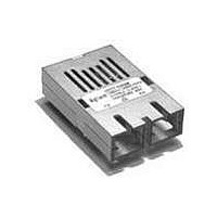
Manufacturer Part Number
HFCT-5208M
Description
TXRX 1X9 622MBIT/S SONET/SDH ATM
Manufacturer
Avago Technologies US Inc.
Datasheet
1.HFBR-5000.pdf
(20 pages)
Specifications of HFCT-5208M
Data Rate
622Mbps
Wavelength
1300nm
Applications
General Purpose
Voltage - Supply
4.75 V ~ 5.25 V
Connector Type
SC
Mounting Type
Through Hole
Function
Designed for implement a range of solutions for ATM/SONET STS-12/SDH, STM-4 Application.
Product
Transceiver
Maximum Rise Time
0.51 ns, 1.25 ns
Maximum Fall Time
0.51 ns, 1.25 ns
Pulse Width Distortion
0.04 ns
Maximum Output Current
50 mA
Operating Supply Voltage
4.75 V to 5.25 V
Maximum Operating Temperature
+ 70 C
Minimum Operating Temperature
0 C
Package / Case
SIP-9
For Use With
Singlemode Glass
Lead Free Status / RoHS Status
Contains lead / RoHS non-compliant


Table 1. Pinout Table
9
Pin
Mounting Studs
1
2
3
5
6
7
8
9
4
1 = V
2 = RD
3 = RD
4 = SD
5 = V
6 = V
7 = TD
8 = TD
9 = V
Symbol
RD+
RD-
SD
V
V
V
TD-
TD+
V
EER
CCR
CCT
EET
EER
CCR
CCT
EET
Functional Description
ground.
Receiver Signal Ground
Directly connect this pin to receiver signal ground plane. Receiver V
Receiver Data Out
input pin.
Receiver Data Out Bar
input pin.
Signal Detect
Normal input optical signal levels to the receiver result in a logic "1" output (V
Low input optical signal levels to the receiver result in a fault condition indication shown by a logic "0"
output (V
If Signal Detect output is not used, leave it open-circuited.
input or Loss of Signal-bar.
Receiver Power Supply
Provide +5 V dc via the recommended receiver V
Locate the power supply filter circuit as close as possible to the V
Provide +5 V dc via the recommended transmitter V
Locate the power supply filter circuit as close as possible to the V
transmitter input pin.
transmitter input pin.
Directly connect this pin to the transmitter signal ground plane. Transmitter V
TOP VIEW
The mounting studs are provided for transceiver mechanical attachment to the circuit boards, they are
embedded in the metalized plastic housing and are not connected to the transceiver internal circuit. They
should be soldered into plated-through holes on the printed circuit board and not connected to signal
common circuit board ground plane.
Terminate this high-speed, differential, PECL output with standard PECL techniques at the follow-on device
Terminate this high-speed, differential, PECL output with standard PECL techniques at the follow-on device
This Signal Detect output can be used to drive a PECL input on an upstream circuit, such as, Signal Detect
Transmitter Power Supply
Transmitter Data In Bar
Terminate this high-speed, differential, Transmitter Data input with standard PECL techniques at the
Transmitter Data In
Terminate this high-speed, differential, Transmitter Data input with standard PECL techniques at the
Transmitter Signal Ground
connect to a common circuit board ground plane.
N/C
N/C
OL
).
N/C = NO INTERNAL CONNECTION
(MOUNTING POSTS) - CONNECT
TO CHASSIS GROUND OR LEAVE
FLOATING, DO NOT CONNECT TO
SIGNAL GROUND.
CCR
power supply filter circuit.
CCT
power supply filter circuit.
CCR
CCT
EER
pin.
pin.
and transmitter V
EET
OH
).
and receiver V
EET
can connect to a
EER
can
Related parts for HFCT-5208M
Image
Part Number
Description
Manufacturer
Datasheet
Request
R

Part Number:
Description:
TXRX SMF XFP 10BGE 2KM OC-192
Manufacturer:
Avago Technologies US Inc.
Datasheet:

Part Number:
Description:
Fiber Optic Transmitters, Receivers, Transceivers OC3 SFP IR -10 to +8 5 non-DMI
Manufacturer:
Avago Technologies US Inc.
Datasheet:

Part Number:
Description:
Fiber Optics, Transceiver Module
Manufacturer:
Avago Technologies US Inc.
Part Number:
Description:
Fiber Optic Transmitters, Receivers, Transceivers SFP OC12 IR Standard Delatch
Manufacturer:
Avago Technologies US Inc.

Part Number:
Description:
Manufacturer:
Avago Technologies
Datasheet:

Part Number:
Description:
155 Mb/s Single Mode Laser Transceiver For Atm, Sonet OC-3/SDH STM-1 (L1.1)
Manufacturer:
Agilent Technologies, Inc.
Datasheet:
Part Number:
Description:
Fiber Optics, Evaluation Kit
Manufacturer:
Avago Technologies US Inc.
Datasheet:
Part Number:
Description:
Fiber Optics, Evaluation Kit
Manufacturer:
Avago Technologies US Inc.
Datasheet:
Part Number:
Description:
Fiber Optics, Evaluation Kit
Manufacturer:
Avago Technologies US Inc.
Datasheet:

Part Number:
Description:
Agilent HFCT-5215B/D 155 Mb/s Single Mode Laser Transceiver
Manufacturer:
Hewlett-Packard
Datasheet:

Part Number:
Description:
OPTOCOUPLER GATE DRV 2A 16-SOIC
Manufacturer:
Avago Technologies US Inc.
Datasheet:
Part Number:
Description:
OPTOCOUPLER 2CH 2.5A 16-SOIC
Manufacturer:
Avago Technologies US Inc.
Datasheet:

Part Number:
Description:
OPTOCOUPLER GATE DRV 0.4A 16SOIC
Manufacturer:
Avago Technologies US Inc.
Datasheet:

Part Number:
Description:
OPTOCOUPLER 2.0A 250KHZ 8-DIP
Manufacturer:
Avago Technologies US Inc.
Datasheet:

Part Number:
Description:
OPTOCOUPLER 2.0A 250KHZ GW 8-SMD
Manufacturer:
Avago Technologies US Inc.
Datasheet: