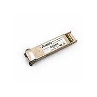
HFCT-711XPD Avago Technologies US Inc., HFCT-711XPD Datasheet - Page 10

HFCT-711XPD
Manufacturer Part Number
HFCT-711XPD
Description
TXRX SMF XFP 10BGE 2KM OC-192
Manufacturer
Avago Technologies US Inc.
Datasheet
1.HFCT-711XPD.pdf
(14 pages)
Specifications of HFCT-711XPD
Data Rate
10.52Gbps
Wavelength
1310nm
Applications
General Purpose
Voltage - Supply
3.135 V ~ 3.465 V
Connector Type
LC Duplex
Mounting Type
Panel Mount
Function
Transceiver for Multirate SONET OC-192 SR1, 10G Base-LR and 10G FC
Product
Transceiver
Maximum Rise Time
24 ps
Maximum Fall Time
24 ps
Operating Supply Voltage
3.135 V to 3.465 V
Maximum Operating Temperature
+ 70 C
Minimum Operating Temperature
- 5 C
Package / Case
XFP-30
For Use With
Singlemode Glass
Lead Free Status / RoHS Status
Contains lead / RoHS non-compliant
Transceiver Internal Temperature
Temperature is measured on the HFCT-711XPD using
sensing circuitry mounted on the internal PCB. The
measured temperature will generally be cooler than laser
junction and warmer than XFP case and can be indirectly
correlated to XFP case or laser junction temperature using
thermal resistance and capacitance modeling. This
measurement can be used to observe drifts in thermal
operating point or to detect extreme temperature
fluctuations such as a failure in the system thermal control.
For more information on correlating internal temperature
to case or laser junction contact Avago Technologies.
Transmitter Laser dc Bias Current
Laser bias current is measured using sensing circuitry
located on the transmitter laser driver IC. Normal
variations in laser bias current are expected to
accommodate the impact of changing transceiver
temperature and supply voltage operating points. The
HFCT-711XPD uses a closed loop laser bias feedback
circuit to maintain constant optical power and extinction
ratio. This circuit compensates for normal laser parametric
variations in quantum efficiency, forward voltage and
lasing threshold due to changing transceiver operating
points.
Figure 5. XFP Assembly Drawing
10
Cage Assembly
Heat Sink
Clip
Module
Host Board
Bezel
Transmitted Average Optical Output Power
Variations in average optical power are not expected
under normal operation because the HFCT-711XPD uses
a closed loop laser bias feedback circuit to maintain
constant optical power. This circuit compensates for
normal laser parametric variations due to changing
transceiver operating points. Only under extreme laser
bias conditions will significant drifting in transmitted
average optical power be observable. Therefore it is
recommended Tx average optical power be used for fault
isolation, rather than predictive failure purposes.
Received Average Optical Input Power
Received average optical power measurements are a
valuable asset for installers to verify cable plant
compliance. Drifts in average power can be observed
from the cable plant and remote transmitter for potential
predictive failure use. Received average optical power
can be used for fault isolation.
Auxilliary Monitors
In addition to the parameters mentioned above, Laser
Temperature and Supply Voltage are also reported as
auxilliary parameters
EMI Gasket
(not shown)
Connector


