HFCT-5208EMZ Avago Technologies US Inc., HFCT-5208EMZ Datasheet - Page 14
HFCT-5208EMZ
Manufacturer Part Number
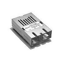
HFCT-5208EMZ
Description
TXRX 1X9 622MBIT/S SONET/SDH ATM
Manufacturer
Avago Technologies US Inc.
Datasheet
1.HFBR-5208Z.pdf
(19 pages)
Specifications of HFCT-5208EMZ
Data Rate
622Mbps
Wavelength
1300nm
Applications
General Purpose
Voltage - Supply
4.75 V ~ 5.25 V
Connector Type
SC
Mounting Type
Through Hole
Function
Designed for implement a range of solutions for ATM/SONET STS-12/SDH, STM-4 Application.
Product
Transceiver
Maximum Rise Time
1.25 ns
Maximum Fall Time
1.25 ns
Pulse Width Distortion
0.04 ns
Maximum Output Current
50 mA
Operating Supply Voltage
4.75 V to 5.25 V
Maximum Operating Temperature
+ 70 C
Minimum Operating Temperature
0 C
For Use With
Singlemode Glass
Lead Free Status / RoHS Status
Lead free / RoHS Compliant


HFBR-5208xxxZ Family, 1300 nm LED
Receiver Optical Characteristics
(T
(T
Notes:
10. This specification is intended to indicate the performance of the receiver section of the transceiver when the input power ranges from the
14
Parameter
Minimum Input Optical Power at window edge
Minimum Input Optical Power at eye center
Input Optical Power Maximum
Input Operating Wavelength
Systematic Jitter Contributed by the Receiver
Random Jitter Contributed by the Receiver
Signal Detect - Asserted
Signal Detect - Deasserted
Signal Detect - Hysteresis
A
A
= 0°C to +70°C, V
= -40°C to +85°C, V
minimum level (with a window time-width) to the maximum level. Over this range the receiver is guaranteed to provide output data with a
Bit Error Ratio (BER) better than or equal to 1 x 10
1.
atic (SJ) and randomjitter (RJ). The worst-case maximum input SJ = 0.5 ns peak-to-peak and the RJ = 0.15 ns peak-to-
peak per ANSI T1.646a standard. Since the input (transmitter) random jitter contribution is very small and difficult to
produce exactly, only the maximum systematic jitter is produced and used for testing the receiver. The corresponding re-
ceiver test window time-width must meet the requirement of 0.31 ns or larger. This worst-case test window time-width
results from the following jitter equation: Minimum Test Window Time-Width = Baud Interval - Tx SJ max. - Rx SJ max. - Rx RJ max.
espectively, Minimum Test Window Time-Width = 1.608 ns - 0.50 ns - 0.30 ns - 0.48 ns = 0.328 ns.
This is a test method that is within practical test error of the worst-case 0.31 ns limit.
receiver sections of the transceiver.
CC
CC
= 4.75 to 5.25 V. Typical @+25°C, 5 V)
23
-1 PRBS data pattern with 72 “1”s and 72 “0”s inserted per the CCITT (now ITU-T) recommendation G.958 Appendix
= 4.75 to 5.25 V. Typical @+25°C, 5 V for A specification part)
-10
Symbol
P
(W)
P
P
l
SJ
RJ
P
P
P
A
A
IN
IN
IN
D
- P
MIN
MIN (C)
MAX
D
Minimum
-14
1270
P
-45
1.0
D
+1.0 dB
Typical
-29.0
-30.5
-11
0.1
0.25
-30.5
-33.7
3.2
Maximum
-26
1380
0.30
0.48
-28
5
Unit
dBm avg.
dBm avg.
dBm avg.
nm
ns p-p
ns p-p
dBm avg.
dBm avg.
dB
Notes
10
Fig 2
10
Fig 2,3
10
-
Related parts for HFCT-5208EMZ
Image
Part Number
Description
Manufacturer
Datasheet
Request
R

Part Number:
Description:
Fiber Optics, Transceiver Module
Manufacturer:
Avago Technologies US Inc.

Part Number:
Description:
Fiber Optic Transmitters, Receivers, Transceivers SFP OC12 IR Standard Delatch
Manufacturer:
Avago Technologies US Inc.

Part Number:
Description:
Manufacturer:
Avago Technologies
Datasheet:

Part Number:
Description:
155 Mb/s Single Mode Laser Transceiver For Atm, Sonet OC-3/SDH STM-1 (L1.1)
Manufacturer:
Agilent Technologies, Inc.
Datasheet:
Part Number:
Description:
Fiber Optics, Evaluation Kit
Manufacturer:
Avago Technologies US Inc.
Datasheet:
Part Number:
Description:
Fiber Optics, Evaluation Kit
Manufacturer:
Avago Technologies US Inc.
Datasheet:
Part Number:
Description:
Fiber Optics, Evaluation Kit
Manufacturer:
Avago Technologies US Inc.
Datasheet:

Part Number:
Description:
Agilent HFCT-5215B/D 155 Mb/s Single Mode Laser Transceiver
Manufacturer:
Hewlett-Packard
Datasheet:

Part Number:
Description:
Agilent HFCT-5905E MT-RJ Duplex Single Mode Transceiver
Manufacturer:
HP [Agilent(Hewlett-Packard)]
Datasheet:
Part Number:
Description:
LC TRANSCEIVER PORT PLUG
Manufacturer:
Avago Technologies US Inc.

Part Number:
Description:
OPTOCOUPLER GATE DRV 2A 16-SOIC
Manufacturer:
Avago Technologies US Inc.
Datasheet:
Part Number:
Description:
OPTOCOUPLER 2CH 2.5A 16-SOIC
Manufacturer:
Avago Technologies US Inc.
Datasheet:

Part Number:
Description:
OPTOCOUPLER GATE DRV 0.4A 16SOIC
Manufacturer:
Avago Technologies US Inc.
Datasheet:

Part Number:
Description:
OPTOCOUPLER 2.0A 250KHZ 8-DIP
Manufacturer:
Avago Technologies US Inc.
Datasheet:

Part Number:
Description:
OPTOCOUPLER 2.0A 250KHZ GW 8-SMD
Manufacturer:
Avago Technologies US Inc.
Datasheet: