HFCT-5208EMZ Avago Technologies US Inc., HFCT-5208EMZ Datasheet
HFCT-5208EMZ
Specifications of HFCT-5208EMZ


Related parts for HFCT-5208EMZ


HFCT-5208EMZ Summary of contents
Page 1
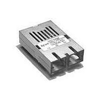
HFBR-5208xxxZ Fiber Optic Transceivers for 622 Mb/s ATM/SONET/SDH Applications Data Sheet Description General The HFBR-5208xxxZ (multimode transceiver) from Avago allow the system designer to implement a range of solu- tions for ATM/SONET STS-12/SDH STM-4 applications. The overall ...
Page 2
Applications Information Typical BER Performance of HFBR-5208xxxZ Receiver versus Input Optical Power Level The HFBR-5208xxxZ transceiver can be operated at Bit- Error-Ratio conditions other than the required BER = 1 - the 622 MBd ATM Forum 622.08 ...
Page 3
311. 622. 650. 1 Figure 2. HFBR-5208xxMZ Relative Input Optical Power as a function of ...
Page 4
Maintain a solid, low inductance ground plane for returning signal currents to the power supply. Multilayer plane printed circuit board is best for distribution of V currents, forming transmission lines and shielding. Also important to suppress noise from ...
Page 5
Reference Design Avago has developed a reference design for multimode ATM-SONET/SDH applications shown in Figure 6. This ref- erence design uses a Vitesse Semiconductor Inc. ’ s VSC8117 clock recovery/clock generation/serializer/deserializer integrated circuit and a PMC-Sierra Inc. PM5355 framer IC. ...
Page 6
Electromagnetic Interference (EMI) One of a circuit board designer’s foremost concerns is the control of electromagnetic emissions from electronic equipment. Success in controlling generated Electromag- netic Interference (EMI) enables the designer to pass a governmental agency’s EMI regulatory standard; and ...
Page 7
KEY: YYW CODE HFBR-5208Z COUNTRY OF ORIGIN YYWW 0.08 0.75 - 0.05 3.30 ± 0.38 + 0.003 10.35 (0.030 ) (0.130 ± 0.015) - 0.002 (0.407) 0.46 ¿ (0.018) NOTE 1 ...
Page 8
An un-shielded option, shown in Figure 7a is available for the HFBR-5208xxxZ fiber optic transceiver. This unit is intended for applications where EMI is either not an issue for the designer, or the unit resides in a highly-shielded enclosure. The ...
Page 9
Electrostatic Discharge (ESD) There are two design cases in which immunity to ESD damage is important. The first case is during handling of the transceiver prior to mounting it on the circuit board important to use normal ESD ...
Page 10
V EER N TOP VIEW CCR CCT N EET Table 1. Pinout Table Pin ...
Page 11
Absolute Maximum Ratings Stresses in excess of the absolute maximum ratings can cause catastrophic damage to the device. Limits apply to each parameter in isolation, all other parameters having values within the recommended operating conditions. It should not be assumed ...
Page 12
HFBR-5208xxxZ Family, 1300 nm LED Transmitter Electrical Characteristics (T = 0°C to +70° 4.75 to 5.25 V. Typical @+25° -40°C to +85° 4.75 to 5.25 V. Typical @+25° ...
Page 13
HFBR-5208xxxZ Family, 1300 nm LED Transmitter Optical Characteristics (T = 0°C to +70° 4.75 to 5.25 V. Typical @+25° -40°C to +85° 4.75 to 5.25 V. Typical @+25° ...
Page 14
HFBR-5208xxxZ Family, 1300 nm LED Receiver Optical Characteristics (T = 0°C to +70° 4.75 to 5.25 V. Typical @+25° -40°C to +85° 4.75 to 5.25 V. Typical @+25° ...
Page 15
KEY: XXXX-XXXX YYWW = DATE CODE FOR MULTIMODE MODULES: XXXX-XXXX = HFBR-5208EMZ COUNTRY OF ORIGIN YYWW TX RX 25.4 MAX. (1.00) +0.1 -0.05 0.25 +0.004 ( ) 0.010 -0.002 9.8 MAX. (0.386) 3.3 ± 0.38 (0.130 ± 0.015) +0.25 -0.05 ...
Page 16
PCB BOTTOM VIEW (0.14) DIMENSIONS ARE IN MILLIMETERS (INCHES). TOLERANCES: X.XX ±0.025 mm UNLESS OTHERWISE SPECIFIED. X.X ±0.05 mm Figure 9. Suggested Module Positioning and Panel Cut-out for HFBR-5208EMZ 16 0.8 2X (0.032) 0.8 2X (0.032) 27.4 ...
Page 17
KEY: XXXX-XXXX YYWW = DATE CODE FOR MULTIMODE MODULES: XXXX-XXXX = HFBR-5208FMZ COUNTRY OF ORIGIN YYWW TX RX 25.4 (1.00) +0.1 -0.05 0.25 +0.004 ( ) 0.010 -0.002 9.8 (0.386) 3.3 ± 0.38 (0.130 ± 0.015) +0.25 -0.05 0.46 9X ...
Page 18
BOTTOM SIDE OF PCB DIMENSIONS ARE IN MILLIMETERS (INCHES). TOLERANCES: X.XX ±0.025 mm UNLESS OTHERWISE SPECIFIED. X.X ±0.05 mm Figure 11. Suggested Module Positioning and Panel Cut-out for HFBR-5208FMZ 18 DIMENSION SHOWN FOR MOUNTING MODULE 1.98 FLUSH TO ...
Page 19
Ordering Information 1300 nm LED (temperature range 0°C to +70°C) HFBR-5208MZ No shield, metallized housing. HFBR-5208EMZ Extended/protruding shield, metallized housing. HFBR-5208FMZ Flush shield, metallized housing. 1300 nm LED (temperature range -40°C to +85°C) HFBR-5208AMZ No shield, metallized housing. HFBR-5208AEMZ Extended/protruding ...