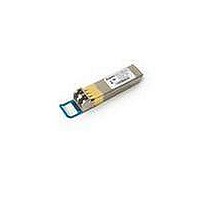
AFCT-57R5APZ Avago Technologies US Inc., AFCT-57R5APZ Datasheet - Page 12

AFCT-57R5APZ
Manufacturer Part Number
AFCT-57R5APZ
Description
TXRX OPT SFP LC 4/2/1GBD LC CONN
Manufacturer
Avago Technologies US Inc.
Series
-r
Datasheet
1.AFCT-57R5APZ.pdf
(20 pages)
Specifications of AFCT-57R5APZ
Data Rate
4.25Gbps
Wavelength
1310nm
Applications
General Purpose
Voltage - Supply
2.97 V ~ 3.63 V
Connector Type
LC Duplex
Mounting Type
SFP
Function
Digital Diagnostic Optical Transceiver, supports high-speed singlemode optical fiber at signaling rates up to 4.25 Gb/s
Product
Transceiver
Maximum Rise Time
0.9 ns/0.15 ns
Maximum Fall Time
0.9 ns/0.15 ns
Pulse Width Distortion
0.06 ns (Max)/0.061 ns (Max)
Operating Supply Voltage
2.97 V to 3.63 V
Maximum Operating Temperature
+ 85 C
Minimum Operating Temperature
- 10 C
Package / Case
SFP
Lead Free Status / RoHS Status
Lead free / RoHS Compliant
For Use With
Singlemode Glass
Lead Free Status / RoHS Status
Lead free / RoHS Compliant, Lead free / RoHS Compliant
Table 9. Transceiver Timing Characteristics
(T
Parameter
Hardware TX_DISABLE Assert Time
Hardware TX_DISABLE Negate Time
Time to initialize, including reset of TX_FAULT
Hardware TX_FAULT Assert Time
Hardware TX_DISABLE to Reset
Hardware RX_LOS DeAssert Time
Hardware RX_LOS Assert Time
Software TX_DISABLE Assert Time
Software TX_DISABLE Negate Time
Software Tx_FAULT Assert Time
Software Rx_LOS Assert Time
Software Rx_LOS De-Assert Time
Analog parameter data ready
Serial bus hardware ready
Write Cycle Time
Serial ID Clock Rate
Notes:
1. Time from rising edge of TX_DISABLE to when the optical output falls below 10% of nominal.
2. Time from falling edge of TX_DISABLE to when the modulated optical output rises above 90% of nominal.
3. Time from power on or falling edge of Tx_Disable to when the modulated optical output rises above 90% of nominal.
4. From power on or negation of TX_FAULT using TX_DISABLE.
5. Time TX_DISABLE must be held high to reset the laser fault shutdown circuitry.
6. Time from loss of optical signal to Rx_LOS Assertion.
7. Time from valid optical signal to Rx_LOS De-Assertion.
8. Time from two-wire interface assertion of TX_DISABLE (A2h, byte 110, bit 6) to when the optical output falls below 10% of nominal. Measured
9. Time from two-wire interface de-assertion of TX_DISABLE (A2h, byte 110, bit 6) to when the modulated optical output rises above 90% of
10. Time from fault to two-wire interface TX_FAULT (A2h, byte 110, bit 2) asserted.
11. Time for two-wire interface assertion of Rx_LOS (A2h, byte 110, bit 1) from loss of optical signal.
12. Time for two-wire interface de-assertion of Rx_LOS (A2h, byte 110, bit 1) from presence of valid optical signal.
13. From power on to data ready bit asserted (A2h, byte 110, bit 0). Data ready indicates analog monitoring circuitry is functional.
14. Time from power on until module is ready for data transmission over the serial bus (reads or writes over A0h and A2h).
15. Time from stop bit to completion of a 1-8 byte write command.
12
C
= -10°C to 85°C, VccT, VccR = 3.3 V ± 10%)
from falling clock edge after stop bit of write transaction.
nominal.
Symbol
t_off
t_on
t_init
t_fault
t_reset
t_loss_on
t_loss_off
t_off_soft
t_on_soft
t_fault_soft
t_loss_on_soft
t_loss_off_soft
t_data
t_serial
t_write
f_serial_clock
Minimum
10
Maximum
10
1
300
100
100
100
100
100
100
100
100
1000
300
10
400
Unit
µs
ms
ms
µs
µs
µs
µs
ms
ms
ms
ms
ms
ms
ms
ms
kHz
Notes
Note 1
Note 2
Note 3
Note 4
Note 5
Note 6
Note 7
Note 8
Note 9
Note 10
Note 11
Note 12
Note 13
Note 14
Note 15


