AFBR-53D5Z Avago Technologies US Inc., AFBR-53D5Z Datasheet - Page 8
AFBR-53D5Z
Manufacturer Part Number
AFBR-53D5Z
Description
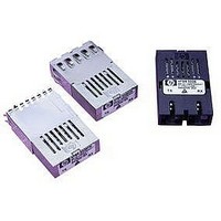
TXRX OPTICAL 5V GBE 1X9
Manufacturer
Avago Technologies US Inc.
Series
-r
Datasheet
1.AFBR-53D5EZ.pdf
(15 pages)
Specifications of AFBR-53D5Z
Applications
Ethernet
Connector Type
SC
Wavelength
850nm
Voltage - Supply
4.75 V ~ 5.25 V
Mounting Type
Through Hole
Supply Voltage
5V
Wavelength Typ
850nm
Leaded Process Compatible
Yes
Data Rate
-
Lead Free Status / RoHS Status
Lead free / RoHS Compliant
Data Rate
-
Lead Free Status / Rohs Status
Lead free / RoHS Compliant


Transmitter Optical Characteristics
(TA = 0°C to +70°C, VCC = 4.75 V to 5.25 V)
Receiver Optical Characteristics
(TA = 0°C to +70°C, VCC = 4.75 V to 5.25 V)
Notes:
1. The maximum Optical Output Power complies with the IEEE 802.3z specification, and is class 1 laser eye safe.
2. Optical Extinction Ratio is defined as the ratio of the average output optical power of the transmitter in the high (“1”) state to the low (“0”)
3. These are unfiltered 20-80% values.
4. Laser transmitter pulse response characteristics are specified by an eye diagram (Figure 1). The characteristics include rise time, fall time,
5. CPR is measured in accordance with EIA/TIA-526-14A as referenced in 802.3z, section 38.6.10.
6. TP refers to the compliance point specified in 802.3z, section 38.2.1.
7. The receive sensitivity is measured using a worst case extinction ratio penalty while sampling at the center of the eye.
8. The stressed receiver sensitivity is measured using the conformance test signal defined in 802.3z, section 38.6.11. The conformance test sig-
9. The stressed receiver jitter is measured using the conformance test signal defined in 802.3z, section 38.6.11 and set to an average optical
10. The 3 dB electrical bandwidth of the receiver is measured using the technique outlined in 802.3z, section 38.6.12.
11. Return loss is defined as the minimum attenuation (dB) of received optical power for energy reflected back into the optical fiber.
Parameter
Output Optical Power
50/125 mm, NA = 0.20 Fiber
Output Optical Power
62.5/125 mm, NA = 0.275 Fiber
Optical Extinction Ratio
Center Wavelength
Spectral Width - rms
Optical Rise / Fall Time
RIN
Coupled Power Ratio
Total Transmitter Jitter Added at TP2
Parameter
Input Optical Power
Stressed Receiver Sensitivity
Stressed Receiver Eye Opening at TP4
Receiver Electrical 3dB Upper Cutoff
Frequency
Operating Center Wavelength
Return Loss
Signal Detect - Asserted
Signal Detect - Deasserted
Signal Detect - Hysteresis
state. The transmitter is driven with a Gigabit Ethernet 1250 MBd 8B/10B encoded serial data pattern. This Optical Extinction Ratio is ex-
pressed in decibels (dB) by the relationship 10log(Phigh avg/Plow avg).
pulse overshoot, pulse undershoot, and ringing, all of which are controlled to prevent excessive degradation of the receiver sensitivity. These
parameters are specified by the referenced Gigabit Ethernet eye diagram using the required filter. The output optical waveform complies
with the requirements of the eye mask discussed in section 38.6.5 and Fig. 38-2 of IEEE 802.3z.
nal is conditioned by applying deterministic jitter and intersymbol interference.
power 0.5 dB greater than the specified stressed receiver sensitivity.
12
Symbol
P
P
l
s
t
CPR
Symbol
P
62.5 µm
50 µm
λ
PA
PD
PA - PD
C
T
OUT
OUT
IM
C
/t
f
Min.
-9.5
-9.5
9
830
9
Min.
-17
201
770
12
-30
15
Typ.
850
Typ.
Max.
-4
-4
860
0.85
0.26
-117
227
Max.
0
- 12.5
- 13.5
1500
860
-18
Unit
dBm avg.
dBm avg.
dBm avg.
ps
MHz
nm
dB
dBm avg.
dBm avg.
db
Unit
dBm
avg.
dBm
avg.
dB
nm
nm rms
ns
dB/Hz
dB
ps
Reference
1
1
2
3, 4, Fig. 1
5
6
Reference
7
8
8
6, 9
10
11
Related parts for AFBR-53D5Z
Image
Part Number
Description
Manufacturer
Datasheet
Request
R

Part Number:
Description:
650nm FE Transceiver Eval Kit
Manufacturer:
Avago Technologies US Inc.
Datasheet:

Part Number:
Description:
TXRX OPT OC3 MTRJ SFF 2X5DIP
Manufacturer:
Avago Technologies US Inc.
Datasheet:

Part Number:
Description:
TXRX ETHERNET 125MBD MMF 2X5
Manufacturer:
Avago Technologies US Inc.
Datasheet:

Part Number:
Description:
TXRX OPT SFP DGTL 850NM IND
Manufacturer:
Avago Technologies US Inc.
Datasheet:

Part Number:
Description:
TXRX OPT SFF 4/2/1GBD 2X7
Manufacturer:
Avago Technologies US Inc.
Datasheet:

Part Number:
Description:
TXRX OPT SFP 4/2/1GBD 850NM
Manufacturer:
Avago Technologies US Inc.
Datasheet:

Part Number:
Description:
TXRX OPT XFP 10GB/S 850NM
Manufacturer:
Avago Technologies US Inc.
Datasheet:

Part Number:
Description:
TXRX OPT 1X9 100MBPS ST EXT TEMP
Manufacturer:
Avago Technologies US Inc.
Datasheet:

Part Number:
Description:
TXRX OPT 1X9 100MBPS SC EXT TEMP
Manufacturer:
Avago Technologies US Inc.
Datasheet:

Part Number:
Description:
TXRX OPT 1X9 100MBPS DUPLEX SC
Manufacturer:
Avago Technologies US Inc.
Datasheet:

Part Number:
Description:
OPTOCOUPLER GATE DRV 2A 16-SOIC
Manufacturer:
Avago Technologies US Inc.
Datasheet:
Part Number:
Description:
OPTOCOUPLER 2CH 2.5A 16-SOIC
Manufacturer:
Avago Technologies US Inc.
Datasheet:

Part Number:
Description:
OPTOCOUPLER GATE DRV 0.4A 16SOIC
Manufacturer:
Avago Technologies US Inc.
Datasheet:

Part Number:
Description:
OPTOCOUPLER 2.0A 250KHZ 8-DIP
Manufacturer:
Avago Technologies US Inc.
Datasheet:

Part Number:
Description:
OPTOCOUPLER 2.0A 250KHZ GW 8-SMD
Manufacturer:
Avago Technologies US Inc.
Datasheet: