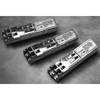
AFBR-59M5LZ Avago Technologies US Inc., AFBR-59M5LZ Datasheet

AFBR-59M5LZ
Specifications of AFBR-59M5LZ
Related parts for AFBR-59M5LZ
AFBR-59M5LZ Summary of contents
Page 1
... SFF MSA (Multi-Source Agreement) , the AFBR-59M5LZ is compliant to SFF-8472 (digital diagnostic interface for optical transceivers). Using the 2-wire serial interface defined in the SFF-8472 MSA, the AFBR-59M5LZ provides real time temperature, supply voltage, laser bias current, laser average output power and received average input power ...
Page 2
... For optical links, the ability to identify a fault at a local device, remote device or cable plant is crucial to speeding service of an installation. AFBR-59M5LZ real-time monitors of Tx_Bias, Tx_Power, Vcc, Temp and Rx average power can be used to assess local transceiver current operating con- ditions. In addition, status fl ...
Page 3
... The contents of A2h, byte 110 bit 6 are logic Or’d with the TX_DISABLE pin to control the transmit output. 3 Eye Safety Circuit The AFBR-59M5LZ provides Class 1 (single fault tolerant) eye safety by design and has been tested for compliance with the requirements listed in Table 1. The eye safety circuit continuously monitors optical output power levels and will disable the transmitter upon detecting an unsafe condition beyond the scope of Class 1 certifi ...
Page 4
... AFBR-59M5LZ. All mechanical adjust- ments are made at the factory before shipping. Tampering with, modifying, misusing or improperly handling the AFBR-59M5LZ will void the product warranty. It may also result in improper operation and possibly overstress the laser source. Performance degradation or device failure may result. Connection of the AFBR-59M5LZ to a light source not compliant to IEEE 802.3 or ANSI FC-PI specifi ...
Page 5
... Table 1. The metal housing and shielded design of the AFBR-59M5LZ minimize the EMI challenge facing the equipment designer. Flammability The AFBR-59M5LZ optical transceiver is made of metal and high strength, heat resistant, chemical resistant and UL 94V-0 flame retardant plastic. EMI Immunity Due to its shielded design, the EMI immunity of the AFBR- 59M5LZ exceeds typical industry standards ...
Page 6
ASIC Tx_DISABLE SERDES IC PROTOCOL IC RX_SD SCL SDA Figure 2. Typical Application Configuration 0.1 μ 0.1 μF 10 μF SFF MODULE HOST BOARD NOTE: INDUCTORS MUST HAVE LESS THAN 1 Ω SERIES RESISTANCE ...
Page 7
Table 2. Pin Description Pin Name Function/Description Receiver Signal Ground Receiver Power Supply: +3. TTL Signal Detect: Active High 4 RD- Received Data Out Bar 5 RD+ Received Data Out ...
Page 8
Table 3. Absolute Maximum Ratings Parameter Storage Temperature Case Operating Temperature Aqueous Wash Pressure Maximum Wave or Flow Soldering Temperature Relative Humidity,non condensing Supply Voltage Voltage to any pin Low Speed Input Voltage Table 4. Recommended Operating Conditions Parameter Case ...
Page 9
Table 6. Transmitter and Receiver Electrical Characteristics (T = -10°C to +70° 3.3 V ± 10 Parameter High Speed Data Input: Transmitter Differential Input Voltage (TD +/-) High Speed Data Output: Receiver ...
Page 10
Table 7. Transmitter Optical Characteristics (T = -10°C to +70° 3.3 V ± 10 Parameter Modulated Optical Output Power (OMA) (Peak-to-Peak) 2.125 Gb/s Modulated Optical Output Power (OMA) (Peak-to-Peak) 1.0625 Gb/s Average ...
Page 11
Table 8. Receiver Optical Characteristics (T = -10°C to +70° 3.3 V ± 10 Parameter Input Optical Power [Overdrive] Input Optical Modulation Amplitude (p-p) 2.125 Gb/s Input Optical Modulation Amplitude (p-p) 1.0625 ...
Page 12
Table 9. Transceiver Soft Diagnostic Timing Characteristics (T = -10°C to +70° 3.3 V ± 10 Parameter Hardware TX_DISABLE Assert Time Hardware TX_DISABLE Negate Time Time to initialize Hardware TX_DISABLE to Reset ...
Page 13
Table 11. Transceiver Digital Diagnostic Monitor (Real Time Sense) Characteristics ( °C to +70 ° 3.3 V ± 10 Parameter Symbol Transceiver (Internal) T INT Temperature Accuracy Transceiver (Internal) V ...
Page 14
... Addresses 63 and 95 are checksums calculated (per SFF-8472 and SFF-8074i) and stored prior to product shipment. 7. Addresses 68-83 specify the AFBR-59M5LZ ASCII serial number and will vary on a per unit basis. 8. Addresses 84-91 specify the AFBR-59M5LZ ASCII date code and will vary on a per date code basis. 14 ...
Page 15
... Transmitted average optical power (Tx Pwr) is decoded bit unsigned integer in increments of 0.1 uW. 5. Received average power (RX Pwr) is decoded bit unsigned integer in increments of 0.1 uW. 6. Bytes 56-94 are not intended for use with AFBR-59M5LZ, but have been set to default values per SFF-8472. 7. Byte checksum calculated (per SFF-8472) and stored prior to product shipment. ...
Page 16
... Data Ready (Bar) Notes: 1. The response time for soft commands of the AFBR-59M5LZ is 100msec as specified by the MSA SFF-8472 2. Bit 6 is logic OR’d with the SFF TX_DISABLE input pin 8 either asserted will disable the SFF transmitter. 3. AFBR-59M5LZ meets the MSA SFF-8472 data ready timing of 1000 msec. ...
Page 17
... Figure 6. Mechanical Drawing - AFBR-59M5LZ +0.15 1.00 0.00 +0.006 0.039 0.000 12.00 REF MAX 0.47 0.00 15.75 - 0.75 0.00 0.62 - 0.03 Figure 7. Assembly Drawing 17 48.8 1.92 16.01 0.63 15.24 MIN PITCH 0.600 A 14.22 ±0.10 0.560 ±0.004 A 1 ...
Page 18
Figure 8. Board Layout For product information and a complete list of distributors, please go to our web site: Avago, Avago Technologies, and the A logo are trademarks of Avago Technologies in the United States and other countries. Data subject ...


