AFBR-5710LZ Avago Technologies US Inc., AFBR-5710LZ Datasheet - Page 9
AFBR-5710LZ
Manufacturer Part Number
AFBR-5710LZ
Description
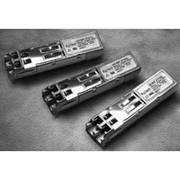
TXRX OPTICAL SFP STD LATCH
Manufacturer
Avago Technologies US Inc.
Series
-r
Datasheet
1.AFBR-5710LZ.pdf
(20 pages)
Specifications of AFBR-5710LZ
Connector Type
LC Duplex
Mounting Type
SFP
Voltage - Supply
3.135 V ~ 3.465 V
Applications
Ethernet
Wavelength
850nm
Data Rate
1.25Gbps
Peak Reflow Compatible (260 C)
Yes
Leaded Process Compatible
Yes
Optical Fiber Type
TX/RX
Data Transfer Rate
1250MBd
Optical Rise Time
0.26/0.22ns
Optical Fall Time
0.26/0.22ns
Jitter
0.227/0.266ns
Operating Temperature Classification
Commercial
Peak Wavelength
850nm
Package Type
SFP
Operating Supply Voltage (min)
3.135V
Operating Supply Voltage (typ)
3.3V
Operating Supply Voltage (max)
3.465V
Operating Temp Range
-10C to 85C
Mounting
Snap Fit To Panel
Pin Count
20
Lead Free Status / RoHS Status
Lead free / RoHS Compliant
Lead Free Status / RoHS Status
Lead free / RoHS Compliant, Lead free / RoHS Compliant
Available stocks
Company
Part Number
Manufacturer
Quantity
Price
Company:

Part Number:
AFBR-5710LZ
Manufacturer:
Avago Technologies US Inc.
Quantity:
135


Table 3. Absolute Maximum Ratings
Table 4. Recommended Operating Conditions
Notes:
1. Recommended Operating Conditions are those within which functional performance within data sheet characteristics is intended.
2. Refer to the Reliability Data Sheet for specific reliability performance predictions.
Table 5. Transceiver Electrical Characteristics
Notes:
1. Measured at the input of the required MSA Filter on host board.
2. Internally AC coupled and terminated to 100 Ω differential load.
3. Internally AC coupled, but requires a 100 Ω differential termination at or internal to Serializer/Deserializer.
4. Pulled up externally with a 4.7-10 KΩ resistor on the host board to V
5. Mod_Def1 and Mod_Def2 must be pulled up externally with a 4.7-10 KΩ resistor on the host board to V
9
Notes:
1. Absolute Maximum Ratings are those values beyond which damage to the device may occur if these limits are exceeded. See Reliability
2. Between Absolute Maximum Ratings and the Recommended Operating Conditions functional performance is not intended, device reliability
3. The module supply voltages, V
Parameter
operating)
Case Temperature
Relative Humidity
Supply Voltage
Low Speed Input Voltage
Parameter
Case Temperature
Supply Voltage
Parameter
Module Supply Current
Power Dissipation
Power Supply Noise
Rejection(peak-peak)
Data input:
Data Output:
Receiver Differential Output
Receive Data Rise & Fall Times
Low Speed Outputs:
of Signal (LOS), MOD_DEF2
Low Speed Inputs:
(TX_DISABLE), MOD_DEF 1,
MOD_DEF 2
Ambient Storage Temperature(Non-
Transmitter Differential Input
Voltage (TD +/-)
Voltage (RD +/-)
Transmit Fault (TX_FAULT) Loss
Transmitter Disable
AFBR-571xLZ/PZ
AFBR-571xALZ/APZ
Data Sheet for specific reliability performance.
is not implied, and damage to the device may occur.
Symbol
T
T
V
CC
C
C
CC
T and V
I
P
PSNR
Symbol
T
V
V
V
V
V
V
CC
DISS
RF
I
O
OH
OL
IH
IL
CC
Minimum
-10
-40
3.135
R, must not differ by more than 0.5V or damage to the device may occur.
Symbol
RH
Ts
T
V
V
C
CCT,R
IN
Minimum
500
370
2.0
0
2.0
0
Minimum
-40
-40
5
-0.5
-0.5
Typical
25
25
3.3
CC
T,R.
160
100
1500
Typical
530
220
Maximum
Maximum
+100
+85
95
3.8
85
85
3.465
V
CC
+0.5
Maximum
0.8
0.8
220
765
2400
2000
V
V
CC
CC
T,R+0.3
CC
T,R.
Unit
°C
°C
V
ps
Unit
mA
mW
mV
mV
mV
V
V
V
V
Unit
°C
°C
%
V
V
PP
PP
PP
Notes
1
2
3
4
5
Notes
1, 2
1, 2
1
1, 2, 3
1
Notes
1, 2
1, 2
1
Related parts for AFBR-5710LZ
Image
Part Number
Description
Manufacturer
Datasheet
Request
R

Part Number:
Description:
650nm FE Transceiver Eval Kit
Manufacturer:
Avago Technologies US Inc.
Datasheet:

Part Number:
Description:
TXRX OPT OC3 MTRJ SFF 2X5DIP
Manufacturer:
Avago Technologies US Inc.
Datasheet:

Part Number:
Description:
TXRX ETHERNET 125MBD MMF 2X5
Manufacturer:
Avago Technologies US Inc.
Datasheet:

Part Number:
Description:
TXRX OPT SFP DGTL 850NM IND
Manufacturer:
Avago Technologies US Inc.
Datasheet:

Part Number:
Description:
TXRX OPT SFF 4/2/1GBD 2X7
Manufacturer:
Avago Technologies US Inc.
Datasheet:

Part Number:
Description:
TXRX OPT SFP 4/2/1GBD 850NM
Manufacturer:
Avago Technologies US Inc.
Datasheet:

Part Number:
Description:
TXRX OPT XFP 10GB/S 850NM
Manufacturer:
Avago Technologies US Inc.
Datasheet:

Part Number:
Description:
TXRX OPT 1X9 100MBPS ST EXT TEMP
Manufacturer:
Avago Technologies US Inc.
Datasheet:

Part Number:
Description:
TXRX OPT 1X9 100MBPS SC EXT TEMP
Manufacturer:
Avago Technologies US Inc.
Datasheet:

Part Number:
Description:
TXRX OPT 1X9 100MBPS DUPLEX SC
Manufacturer:
Avago Technologies US Inc.
Datasheet:

Part Number:
Description:
OPTOCOUPLER GATE DRV 2A 16-SOIC
Manufacturer:
Avago Technologies US Inc.
Datasheet:
Part Number:
Description:
OPTOCOUPLER 2CH 2.5A 16-SOIC
Manufacturer:
Avago Technologies US Inc.
Datasheet:

Part Number:
Description:
OPTOCOUPLER GATE DRV 0.4A 16SOIC
Manufacturer:
Avago Technologies US Inc.
Datasheet:

Part Number:
Description:
OPTOCOUPLER 2.0A 250KHZ 8-DIP
Manufacturer:
Avago Technologies US Inc.
Datasheet:

Part Number:
Description:
OPTOCOUPLER 2.0A 250KHZ GW 8-SMD
Manufacturer:
Avago Technologies US Inc.
Datasheet: