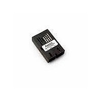
AFBR-5805Z Avago Technologies US Inc., AFBR-5805Z Datasheet - Page 8

AFBR-5805Z
Manufacturer Part Number
AFBR-5805Z
Description
TXRX ATM SONET OC3 3V SC 1X9
Manufacturer
Avago Technologies US Inc.
Series
-r
Specifications of AFBR-5805Z
Wavelength
1310nm
Applications
General Purpose
Voltage - Supply
3.3V
Connector Type
SC
Mounting Type
Through Hole
Function
Provides the system designer with products to implement a range of soluntions for multimode fiber SONET OC-3 (SDH STM-1)
Product
Transceiver
Data Rate
155 Mbps
Maximum Rise Time
3 ns/2.2 ns
Maximum Fall Time
3 ns/2.2 ns
Pulse Width Distortion
1.2 ns (Max)/1.91 ns (Max)
Maximum Output Current
50 mA
Operating Supply Voltage
3.135 V to 3.5 V or 4.75 V to 5.25 V
Maximum Operating Temperature
+ 70 C
Minimum Operating Temperature
0 C
Package / Case
SIP-9
Lead Free Status / RoHS Status
Lead free / RoHS Compliant
For Use With
Multimode Glass
Lead Free Status / RoHS Status
Lead free / RoHS Compliant, Lead free / RoHS Compliant
Available stocks
Company
Part Number
Manufacturer
Quantity
Price
Company:
Part Number:
AFBR-5805Z
Manufacturer:
Avago Technologies
Quantity:
135
Board Layout - Hole Pattern
The Avago Technologies transceiver complies with the
circuit board “Common Transceiver Footprint” hole pat-
tern defined in the original multisource announcement
which defined the 1 x 9 package style. This drawing is
reproduced in Figure 8 with the addition of ANSI Y14.5M
compliant dimensioning to be used as a guide in the
mechanical layout of your circuit board.
Board Layout - Mechanical
For applications interested in providing a choice of
either a duplex SC or a duplex ST connector interface,
while utilizing the same pinout on the printed circuit
board, the ST port needs to protrude from the chassis
panel a minimum of 9.53 mm for sufficient clearance to
install the ST connector.
Please refer to Figure 8a for a mechanical layout detail-
ing the recommended location of the duplex SC and
duplex ST transceiver packages in relation to the chassis
panel.
Figure 8a. Recommended Common Mechanical Layout for SC and
ST 1 x 9 Connectored Transceivers.
(0.800)
0.51
0.75
Figure 8. Recommended Board Layout Hole Pattern
20.32
(0.100)
NOTE 1: MINIMUM DISTANCE FROM FRONT
OF CONNECTOR TO THE PANEL FACE.
2.54
11.1
12.0
TOP VIEW
(0.800)
20.32
(NOTE 1)
9.53
6.79
DIMENSIONS ARE IN MILLIMETERS (INCHES)
42.0
39.12
(0.075 ± 0.004)
2 x Ø 1.9 ± 0.1
(0.032 ± 0.004)
9 x Ø 0.8 ± 0.1
24.8
25.4
25.4


