FTLX1471D3BCL Finisar Corporation, FTLX1471D3BCL Datasheet - Page 3
FTLX1471D3BCL
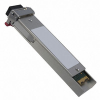
Manufacturer Part Number
FTLX1471D3BCL
Description
TXRX SFP+ SGL 10GB/S 1310NM
Manufacturer
Finisar Corporation
Datasheet
1.FTLX1471D3BCL.pdf
(11 pages)
Specifications of FTLX1471D3BCL
Data Rate
10Gbps
Wavelength
1310nm
Applications
Ethernet
Voltage - Supply
3.3V
Connector Type
LC Duplex
Mounting Type
SFP+
Lead Free Status / RoHS Status
Lead free / RoHS Compliant
Other names
775-1061
Available stocks
Company
Part Number
Manufacturer
Quantity
Price
Company:

Part Number:
FTLX1471D3BCL
Manufacturer:
MICROCHIP
Quantity:
101
Company:
Part Number:
FTLX1471D3BCL
Manufacturer:
Finisar Corporation
Quantity:
135
Part Number:
FTLX1471D3BCL
Manufacturer:
FINOSAR
Quantity:
20 000


FTLX1471D3BCL Datacom SFP+ Product Specification – February 2009
II. Absolute Maximum Ratings
Exceeding the limits below may damage the transceiver module permanently.
Maximum Supply Voltage
Storage Temperature
Relative Humidity
1. Non-condensing.
III.
Supply Voltage
Supply Current
Transmitter
Input differential impedance
Differential data input swing
Transmit Disable Voltage
Transmit Enable Voltage
Receiver
Differential data output swing
Output rise time and fall time
LOS Fault
LOS Normal
Power Supply Noise Tolerance
Notes:
1. Connected directly to TX data input pins. AC coupling from pins into laser driver IC.
2. Into 100Ω differential termination.
3.
4. LOS is an open collector output. Should be pulled up with 4.7kΩ – 10kΩ on the host board. Normal
5. See Section 2.8.3 of SFF-8431 Rev 3.0.
6. The FTLX1471D3BCL is a “limiting module”, i.e., it employs a limiting receiver. Host board designers
IV.
Transmitter
Optical Modulation Amplitude
(OMA)
Average Launch Power
Optical Wavelength
Side-Mode Suppression Ratio
Optical Extinction Ratio
Transmitter and Dispersion Penalty
Average Launch power of OFF
transmitter
Tx Jitter
Relative Intensity Noise
© Finisar Corporation - February 2009
20 – 80%. Measured with Module Compliance Test Board and OMA test pattern. Use of four 1’s and
four 0’s sequence in the PRBS 9 is an acceptable alternative. SFF-8431 Rev 3.0.
operation is logic 0; loss of signal is logic 1.
using an EDC PHY IC should follow the IC manufacturer’s recommended settings for interoperating
the host-board EDC PHY with a limiting receiver SFP+ module.
Electrical Characteristics
Optical Characteristics
Parameter
Parameter
Parameter
(T
Symbol
(T
SMSR
OP
P
P
TDP
P
RIN
ER
Tx
OP
OMA
AVE
λ
OFF
= -5 to 70 °C, V
j
= -5 to 70 °C, V
VccT/VccR
V
Symbol
Vout,pp
V
Symbol
Vin,pp
Rev.C
T
LOS norm
LOS fault
Vcc
V
Vcc
Icc
R
V
RH
r
T
, T
EN
in
D
S
1260
Min
-5.2
-8.2
f
3.5
30
CC3
CC
Min
-0.5
Per 802.3ae requirements
-40
Min
3.14
Vee
Vee
180
300
0
= 3.14 to 3.46 Volts)
28
= 3.14 to 3.46 Volts)
Per SFF-8431 Rev 3.0
2
2
Typ
Typ
3.30
Typ
100
200
Max
1355
+0.5
-128
-30
3.2
Vee+ 0.8
Vee+0.8
Vcc
Max
Max
3.46
Vcc
285
700
850
4.0
85
85
HOST
dB/Hz
Unit
dBm
dBm
dBm
nm
dB
dB
dB
mVpp
Unit
Unit
mA
mV
mV
°C
ps
V
Ω
V
V
V
V
%
V
Page 3
Ref.
1
Ref.
Ref.
2,6
1
1
4
3
4
5
Related parts for FTLX1471D3BCL
Image
Part Number
Description
Manufacturer
Datasheet
Request
R

Part Number:
Description:
1X9 DWP9F, FLEXGRID, C-BAND, LC CONNECTORS, WAVELENGTH SPACING ENABLES HETE
Manufacturer:
Finisar Corporation
Part Number:
Description:
1X9 DWP50, FIXED 50GHZ CHANNEL SPACING (96CH), C-BAND, LC CONNECTORS
Manufacturer:
Finisar Corporation
Part Number:
Description:
DWDM BROADBAND TUNABLE, 50GHZ SPACING (C-BAND), APD, ITU G.698.1, 10GE, 10G
Manufacturer:
Finisar Corporation
Part Number:
Description:
Power cables for 1RU Power Booster product
Manufacturer:
Finisar Corporation
Part Number:
Description:
1X9 DWP100, 50 OR 100GHZ CHANNEL SPACING (48/96CH), C-BAND, LC CONNECTORS
Manufacturer:
Finisar Corporation
Part Number:
Description:
NRZ-DPSK, UP TO 44.6GB/S TRANSPONDER, VERY LONG HAUL, RX. USING FSR = 66.7G
Manufacturer:
Finisar Corporation
Part Number:
Description:
1550NM EML, PIN, NRZ, OTU3, 43GB/S TRANSPONDER, SINGLE MODE, 300-PIN 3.5X4
Manufacturer:
Finisar Corporation
Part Number:
Description:
C-BAND TUNABLE LASER BUTTERFLY PACKAGE, 89 CHANNELS AT 50 GHZ SPACING FROM
Manufacturer:
Finisar Corporation
Part Number:
Description:
1310NM DFB LC TOSA, 10GBPS, LR
Manufacturer:
Finisar Corporation
Datasheet:
Part Number:
Description:
DWDM CML, 100GHZ SPACING (C-BAND OR L-BAND), OC-192, STM64, 10G FC, G.709
Manufacturer:
Finisar Corporation
Part Number:
Description:
1550NM CML, OC-192, STM-64, 10G FC, G.709, 10.7 GB/S, G.959.1 P1L1 AND P1V1
Manufacturer:
Finisar Corporation
Part Number:
Description:
DWDM CML, 8X50GHZ SPACING (C-BAND OR L-BAND), OC-192, STM-64, 10G FC, G.709
Manufacturer:
Finisar Corporation
Part Number:
Description:
1550NM CML, OC-192, STM-64, 10G FC, G.709, 10.7 GB/S, G.959.1 P1L1 AND P1V1
Manufacturer:
Finisar Corporation
Part Number:
Description:
DWDM CML, 100GHZ SPACING (C-BAND OR L-BAND), OC-192, STM-64, 10G FC, G.709
Manufacturer:
Finisar Corporation
Part Number:
Description:
1550NM CML, OC-192, STM-64, 10G FC, G.709, 10.7 GB/S, G.959.1 P1L1 AND P1V1
Manufacturer:
Finisar Corporation