FTLX1471D3BCL Finisar Corporation, FTLX1471D3BCL Datasheet - Page 2
FTLX1471D3BCL
Manufacturer Part Number
FTLX1471D3BCL
Description
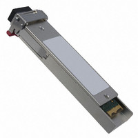
TXRX SFP+ SGL 10GB/S 1310NM
Manufacturer
Finisar Corporation
Datasheet
1.FTLX1471D3BCL.pdf
(11 pages)
Specifications of FTLX1471D3BCL
Data Rate
10Gbps
Wavelength
1310nm
Applications
Ethernet
Voltage - Supply
3.3V
Connector Type
LC Duplex
Mounting Type
SFP+
Lead Free Status / RoHS Status
Lead free / RoHS Compliant
Other names
775-1061
Available stocks
Company
Part Number
Manufacturer
Quantity
Price
Company:

Part Number:
FTLX1471D3BCL
Manufacturer:
MICROCHIP
Quantity:
101
Company:
Part Number:
FTLX1471D3BCL
Manufacturer:
Finisar Corporation
Quantity:
135
Part Number:
FTLX1471D3BCL
Manufacturer:
FINOSAR
Quantity:
20 000


FTLX1471D3BCL Datacom SFP+ Product Specification – February 2009
I.
Notes:
1. Circuit ground is internally isolated from chassis ground.
2. T
3. Laser output disabled on T
4. Internally pulled down per SFF-8431 Rev 2.0.
5. LOS is open collector output. Should be pulled up with 4.7k – 10kΩ on host board to a voltage
© Finisar Corporation - February 2009
Pin
10
11
12
13
14
15
16
17
18
19
20
1
2
3
4
5
6
7
8
9
the host board if intended for use. Pull up voltage should be between 2.0V to Vcc + 0.3V. A high
output indicates a transmitter fault caused by either the TX bias current or the TX output power
exceeding the preset alarm thresholds. A low output indicates normal operation. In the low state, the
output is pulled to <0.8V.
between 2.0V and 3.6V. Logic 0 indicates normal operation; logic 1 indicates loss of signal.
FAULT
Pin Descriptions
MOD_ABS
RX_LOS
Symbol
is an open collector/drain output, which should be pulled up with a 4.7k – 10k Ohms resistor on
T
Figure 1. Diagram of Host Board Connector Block Pin Numbers and Names.
SDA
V
V
RD+
V
V
V
V
SCL
V
TD+
V
RS0
RS1
RD-
T
TD-
FAULT
CCR
CCT
EET
DIS
EER
EER
EER
EET
EET
Towards
Transmitter Ground
Transmitter Fault
Transmitter Disable. Laser output disabled on high or open.
2-wire Serial Interface Data Line
2-wire Serial Interface Clock Line
Module Absent. Grounded within the module
Rate Select 0. Not Used.
Loss of Signal indication. Logic 0 indicates normal operation.
Rate Select 1. Not Used.
Receiver Ground
Receiver Ground
Receiver Inverted DATA out. AC Coupled.
Receiver Non-inverted DATA out. AC Coupled.
Receiver Ground
Receiver Power Supply
Transmitter Power Supply
Transmitter Ground
Transmitter Non-Inverted DATA in. AC Coupled.
Transmitter Inverted DATA in. AC Coupled.
Transmitter Ground
Bezel
DIS
>2.0V or open, enabled on T
10
1
2
3
4
5
6
7
8
9
VeeT
TX_Fault
TX_Disable
RS0
RX_LOS
RS1
VeeR
SDA
SCL
MOD_ABS
Rev.C
Name/Description
VeeT
TD-
TD+
VeeT
VccT
VccR
VeeR
RD+
RD-
VeeR
DIS
20
19
18
17
14
12
11
16
15
13
<0.8V.
Towards
ASIC
Page 2
Ref.
1
2
3
2
2
2
4
5
4
1
1
1
1
1
Related parts for FTLX1471D3BCL
Image
Part Number
Description
Manufacturer
Datasheet
Request
R

Part Number:
Description:
1X9 DWP9F, FLEXGRID, C-BAND, LC CONNECTORS, WAVELENGTH SPACING ENABLES HETE
Manufacturer:
Finisar Corporation
Part Number:
Description:
1X9 DWP50, FIXED 50GHZ CHANNEL SPACING (96CH), C-BAND, LC CONNECTORS
Manufacturer:
Finisar Corporation
Part Number:
Description:
DWDM BROADBAND TUNABLE, 50GHZ SPACING (C-BAND), APD, ITU G.698.1, 10GE, 10G
Manufacturer:
Finisar Corporation
Part Number:
Description:
Power cables for 1RU Power Booster product
Manufacturer:
Finisar Corporation
Part Number:
Description:
1X9 DWP100, 50 OR 100GHZ CHANNEL SPACING (48/96CH), C-BAND, LC CONNECTORS
Manufacturer:
Finisar Corporation
Part Number:
Description:
NRZ-DPSK, UP TO 44.6GB/S TRANSPONDER, VERY LONG HAUL, RX. USING FSR = 66.7G
Manufacturer:
Finisar Corporation
Part Number:
Description:
1550NM EML, PIN, NRZ, OTU3, 43GB/S TRANSPONDER, SINGLE MODE, 300-PIN 3.5X4
Manufacturer:
Finisar Corporation
Part Number:
Description:
C-BAND TUNABLE LASER BUTTERFLY PACKAGE, 89 CHANNELS AT 50 GHZ SPACING FROM
Manufacturer:
Finisar Corporation
Part Number:
Description:
1310NM DFB LC TOSA, 10GBPS, LR
Manufacturer:
Finisar Corporation
Datasheet:
Part Number:
Description:
DWDM CML, 100GHZ SPACING (C-BAND OR L-BAND), OC-192, STM64, 10G FC, G.709
Manufacturer:
Finisar Corporation
Part Number:
Description:
1550NM CML, OC-192, STM-64, 10G FC, G.709, 10.7 GB/S, G.959.1 P1L1 AND P1V1
Manufacturer:
Finisar Corporation
Part Number:
Description:
DWDM CML, 8X50GHZ SPACING (C-BAND OR L-BAND), OC-192, STM-64, 10G FC, G.709
Manufacturer:
Finisar Corporation
Part Number:
Description:
1550NM CML, OC-192, STM-64, 10G FC, G.709, 10.7 GB/S, G.959.1 P1L1 AND P1V1
Manufacturer:
Finisar Corporation
Part Number:
Description:
DWDM CML, 100GHZ SPACING (C-BAND OR L-BAND), OC-192, STM-64, 10G FC, G.709
Manufacturer:
Finisar Corporation
Part Number:
Description:
1550NM CML, OC-192, STM-64, 10G FC, G.709, 10.7 GB/S, G.959.1 P1L1 AND P1V1
Manufacturer:
Finisar Corporation